

1. OSI Model
About the OSI seven-layer model: Application layer, Presentation layer, Session layer, Transport layer, Network layer, Data Link layer, and Physical layer. The seven-layer model and the protocols applied at each layer are shown in the figure below.
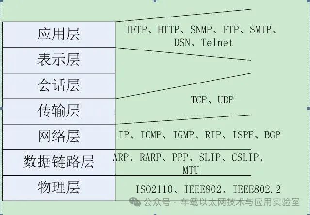
So what protocols are used at each layer? We list some commonly used protocols in the figure below, along with their classification in different protocols at each layer.
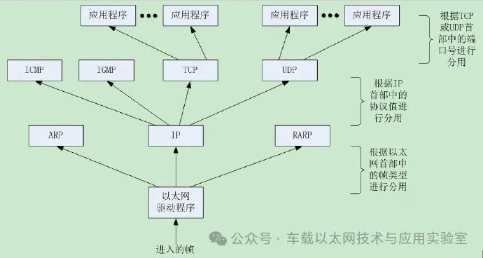
The functions of several commonly used protocols are illustrated through a vivid analogy:
IP: I want to send data to 127.127.127.127
UDP: I want to send a datagram on port N
TCP: I want to send data in a reliable way on port N
ARP: Who knows the MAC address of 127.127.127.127?
RARP: Who knows the IP address of 21.21.12.21?
ICMP: I send or receive queries or error messages
DHCP/BOOTP: I want to get an IP address
DNS: What is the IP address of www.st.com?
The data coming from the network is stripped layer by layer (the encapsulation done by various protocols) to obtain the actual data we need. Sending data over the network also involves adding various protocol headers (encapsulation) before it starts being sent. Below, we will look at the IP–TCP structure of packets on the network, so we can better analyze and parse the actual data.
We will explain using the example of receiving data from Ethernet.
2. Protocol Headers
2.1 Ethernet Header
The first thing we see when receiving data from Ethernet is the Ethernet header, which is 14 bytes long. Its structure is as follows:
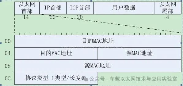
Destination MAC Address: 6 bytes, the MAC address of the device that will receive the network packet. If the least significant bit of the first byte of the MAC address is 0, then this address is a unicast address; if the least significant bit is 1, then this address is a multicast address, and packets with a multicast destination address will be delivered to a selected group of Ethernet nodes; if the destination address field is the reserved multicast address FF-FF-FF-FF-FF-FF, then this packet is a broadcast packet that will be sent to every node sharing the network.
Source MAC Address: 6 bytes, the MAC address of the device sending this packet on the network.
Protocol Type: A two-byte field that defines the protocol to which the following packet belongs. 0800 indicates the IP protocol, 0806 indicates the ARP protocol, and 8035 indicates the RARP protocol. Additionally, if the value in this field is less than or equal to 05DCh (1500), then this field is a length field that specifies the length of non-padded data in the data field.
Note: MAC is the hardware address of the network card, which is hard-coded at the factory. It consists of two parts: the first three bytes are called the Organizationally Unique Identifier (OUI), which is assigned by the ICCC. The last three bytes are defined by the company that purchased the OUI. The Ethernet trailer is a 4-byte CRC check (Frame Check Sequence (FCS)). If the frame length is less than 64 bytes, padding is required to make the frame length reach 64 bytes.
2.2 IP (Network Protocol) Header
Next is the IP header, which is 20 bytes long. Its structure is as follows:
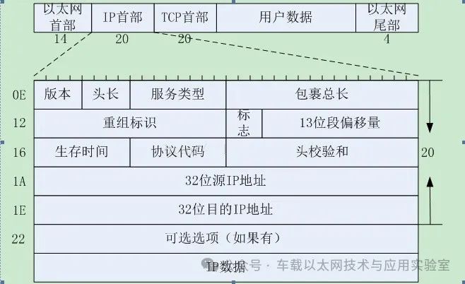
Version: A 4-bit version number, with the most widely used being 4 (1000), which is IPv4;
Header Length: A 4-bit length of the header, measured in 4-byte units, with a minimum value of 5, meaning the minimum header length is 20 bytes. The header length shown in the figure above is 20 bytes, without any options in the IP header, with a maximum header length of 4*15=60 bytes.
Type of Service: An 8-bit TOS field with 3 bits to specify the priority of the IP datagram (which is now deprecated), and 4 bits representing optional service types (minimum delay, maximum throughput, maximum reliability, minimum cost), and one bit that is always 0.
Total Length: The total length of the current packet (including IP header and IP data).
Identification: An identifier assigned by the sending host, which increments by 1 for each IP datagram sent and can be used for fragmentation and reassembly of datagrams.
Flags: A 3-bit flag,
1 bit reserved;
1 bit for the Don’t Fragment flag: 0 means fragmentation is allowed, 1 means it is not allowed;
1 bit for the More Fragments flag: 0 means there are no more packets after this one, indicating this is the last packet, 1 means there are more packets after this one.
Fragment Offset: A 13-bit fragment offset combined with the More Fragments flag, helping the receiver to reassemble the fragmented message.
Time to Live: The TTL seen in the PING command is this. It decreases by 1 for each router it passes. If it reaches 0, it indicates that the route has been too long and the destination host’s network cannot be found, thus the packet is discarded. Therefore, the unit of this time to live is not seconds, but hops.
Protocol Code: The upper-layer protocol using this packet. TCP is 6, ICMP is 1, IGMP is 2, UDP is 17;
Header Checksum: A 16-bit checksum for the IP header.
32-bit Source IP Address and 32-bit Destination IP Address.
2.3 TCP (Transmission Control Protocol) Header
Finally, we have the TCP header, which is 20 bytes long. Its structure is as follows:
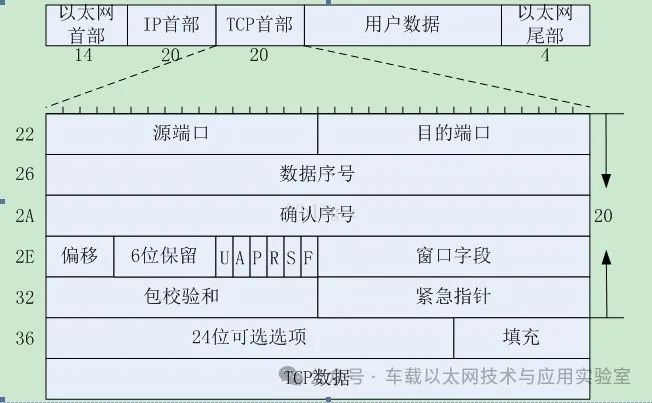
2-byte Source Port and 2-byte Destination Port: Used to identify the sending and receiving application processes. These two values, along with the source IP address and destination IP address in the IP header, uniquely identify a TCP connection. Sometimes, an IP address and a port number are referred to as a socket. This term appeared in the earliest TCP specifications (RFC793) and later became associated with the Berkeley version of the programming interface. A socket pair (including the client’s IP address, client’s port number, server’s IP address, and server’s port number) can uniquely identify both sides of each TCP connection in the Internet.
Data Sequence Number: TCP assigns a number to each byte sent, storing the sequence number of the first byte of the current packet here. If the byte stream is viewed as a one-way flow between two applications, TCP counts each byte with a sequence number.
Acknowledgment Number: TCP tells the receiver the sequence number of the first byte it expects to receive in the next packet.
Offset: A 4-bit offset, similar to IP, indicating how many 32-bit words are in the packet header;
6 Flag Bits:
U: URG urgent bit. When URG=1, it indicates that this segment has urgent data that should be sent as soon as possible;
A: ACK acknowledgment bit. The acknowledgment field is only valid when ACK=1 (TCP three-way handshake);
P: PSH used to notify that a higher data throughput is required, and data must be communicated at a higher rate if possible;
R: RST reset bit. Indicates that a serious error occurred during the TCP connection process, and the connection must be released and then re-established (TCP three-way handshake);
S: SYN synchronization bit. Indicates that this is a connection request or connection acceptance message;
F: FIN termination bit. Indicates that the sender of this segment has finished sending data and requests to release the connection.
Window Field: Used to control the amount of data sent by the other party, measured in bytes. The size of the reception window for a TCP connection is determined according to the size of the set buffer space and then notified to the other party to determine the upper limit of the other party’s sending window;
Packet Checksum: Includes both header and data parts. When calculating the checksum, a 12-byte pseudo-header is added to the front of the TCP segment.
Urgent Pointer: Indicates the sequence number of the last byte of urgent data in this segment.
2.4 ARP (Address Resolution Protocol) Header
For ARP and RARP packets, the ARP or RARP header immediately follows the Ethernet header, and it is 28 bytes long. Its structure is as follows:
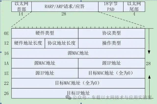
Hardware Type: Indicates the type of hardware address, with a value of 1 indicating Ethernet address.
Protocol Type: Indicates the type of protocol address to be mapped. Its value is 0x0800, indicating an IP address. This value is the same as the type field value in the Ethernet data frame containing the IP datagram, which is by design.
Hardware Address Length and Protocol Address Length indicate the lengths of hardware and protocol addresses in bytes, respectively. For ARP requests or responses for IP addresses over Ethernet, their values are 6 and 4, respectively.
Operation Type indicates four types of operations: ARP request (value 1), ARP response (value 2), RARP request (value 3), and RARP response (value 4). This field is necessary because the frame type field values for ARP requests and RARP responses are the same.
The subsequent content is the repeated MAC and IP addresses.
For an ARP request, all fields except the destination hardware address are filled. When the system receives an ARP request message with the destination being itself, it fills in the hardware address, replaces the two sender addresses with its own IP address and MAC address, sets the operation field to 2, and finally sends it back.
2.5 UDP (User Datagram Protocol) Header
For UDP packets, the UDP header follows the IP header. The UDP header is 8 bytes long, and its structure is as follows:
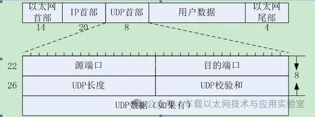
UDP Length: Includes both header and data parts.
Checksum: Covers the UDP header and UDP data.
Note: Both UDP datagrams and TCP segments contain a 12-byte pseudo-header, which is set for checksum calculation and includes some fields from the IP header. TCP has a timeout retransmission mechanism, while UDP does not.
For issues regarding the UDP pseudo-header, please refer to this blog post by a fellow blogger: Detailed Explanation of TCP & UDP Pseudo-Headers.
2.6 ICMP (Internet Control Message Protocol) Header
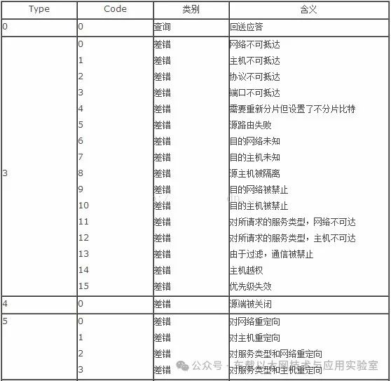
ICMP is at the same layer as IP in the TCP/IP protocol stack. It is encapsulated in IP data. The ICMP header is 8 bytes long, and its structure is as follows:
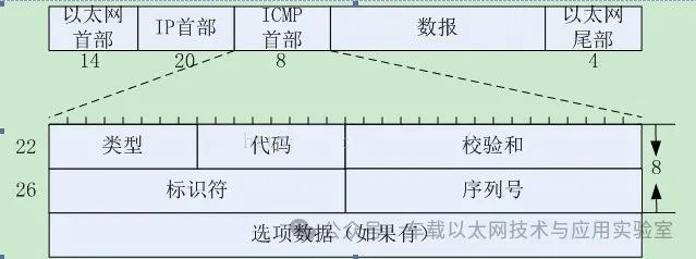
Type: An 8-bit message type used to identify the message.
Code: An 8-bit code used to provide further information about the type.
Checksum: A 16-bit checksum that only covers the ICMP message.
The above 4 bytes are constant in ICMP messages, while the content that follows varies according to the different ICMP functions.
Identifier: Used to represent this ICMP process.
Sequence Number: Used to identify echo reply packets.
3. Common ICMP Messages
1) Response Message (Type 8 or 0, Code 0)
The PING we commonly use is a response request (8) and reply (0). A host sends an ICMP message of type 8 to a node. If there are no exceptions, it returns an ICMP message of type 0, indicating that this host exists.
2) Timestamp Message (Type 13 and 14)
Request 13 and Reply 14, used to test the round-trip transmission time of datagrams between two machines (hosts on the network are generally independent, each machine has its own current time. Timestamp requests and replies are used to query the current time of the destination host system. The return value is the number of milliseconds since midnight, which is used to synchronize time. In fact, due to latency, this value is not accurate, and usually, the average value is obtained by multiple measurements.)
4. About MAC, IP, and Ports
MAC must be unique within a local area network; otherwise, it will conflict with other hosts and cause connection failures.
Like MAC, IP must also be unique within a local area network and cannot conflict with other hosts’ IP addresses. The IP of the development board must be in the same subnet as our computer’s IP, meaning the first three segments of the IP address must match, while the last segment must be different.
For specific packet operations, please refer to the next blog post: Analysis of STM32 Ethernet Program Part One.
5. A Brief Discussion on the Relationship Between IP Addresses, MAC Addresses, and the Address Resolution Protocol (ARP)
ARP (Address Resolution Protocol) is a TCP/IP protocol used to obtain the physical address based on the IP address. The OSI model divides network work into seven layers, with the IP address at the third layer and the MAC address at the second layer, which do not interact directly. When sending IP datagrams over Ethernet, it is necessary to first encapsulate the header of the third layer (32-bit IP address) and the second layer (48-bit MAC address), but since we only know the target IP address when sending, we do not know its MAC address and cannot cross the second and third layers, so we need to use the Address Resolution Protocol. By using ARP, we can resolve the target hardware address (MAC address) information based on the IP address information in the IP datagram header to ensure smooth communication.
RARP (Reverse Address Resolution Protocol) is the reverse address conversion protocol. The reverse address conversion protocol converts the physical address of a host in a local area network to an IP address. For example, if there is a host in the local area network that only knows its physical address but does not know its IP address, it can issue a broadcast request for its own IP address using the RARP protocol, and the RARP server will be responsible for answering.
Assuming there are two hosts, the local host A and the target host B, that need to communicate.
1) The Process of ARP Mapping IP Addresses and MAC Addresses
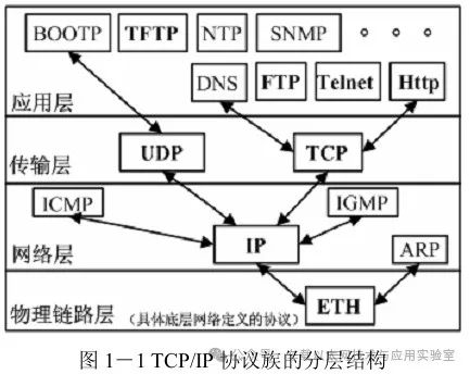
Figure 1-1 shows the layered structure of the TCP/IP protocol family. Packets are often sent over Ethernet, and during the process of sending packets, the IP frame header information is first encapsulated, followed by the MAC address of the link layer, and finally the Ethernet frame header information. The Ethernet frame includes: destination address, source address, and frame type. Ethernet device addresses are 48 bits long; they do not recognize 32-bit IP addresses (IPV4), only MAC addresses. Since Ethernet only recognizes the MAC address of the device, the question arises: we know the source address, which is the MAC address of host A, but what about the target MAC address? We may know it or we may not. How do we obtain the target MAC address? The Address Resolution Protocol will complete the mapping between IP addresses and MAC addresses to obtain the MAC address of host B, which is the specialty of the Address Resolution Protocol.
First, host A determines the IP address of host B based on the routing table, and then checks the ARP cache on its own machine to see if there is a historical record of the MAC address corresponding to host B’s IP address. If there is, it adds it to the destination address of the Ethernet frame. If there is no MAC address corresponding to host B’s IP in the ARP table, host A will broadcast an ARP request frame (containing the IP address of host B, as well as its own IP address and MAC address) to all hosts in the local network. Each host that receives the ARP request will compare the target IP address in the received request frame with its own IP address. If it does not match, the ARP request will be discarded. If it matches, host B will reply with its IP address and MAC address to host A that sent the request, and at the same time, host B will update or record the IP address and MAC address of host A in its ARP table.
When host A receives data, it first checks the type of the frame. From Figure 1-1, it can be seen that the received data may be IP data or ARP data. If the received data is IP data, it will be decoded according to the IP data frame format. If the received data is an ARP data frame, it will determine whether it is a response frame or a request frame. If it is a response frame, host A will update its local ARP table. If it is a request frame, it will reply with host A’s IP address and MAC address to the host that sent the request.
2) Format of ARP Frames
ARP request and response frames have the same format. The destination address of the ARP request frame is the broadcast address: FF:FF:FF:FF:FF:FF
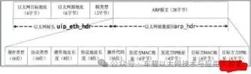
Hardware Type: The type of network on which the ARP protocol is implemented, with the hardware type for Ethernet being 1.
Protocol Type: The protocol type using ARP or RARP, with the IPV4 value being 0x0800.
Hardware Address Length: The length of the physical address, which is 6 for Ethernet.
Protocol Address Length: The length of the protocol address, which is 4 for IPV4.
Operation Code: Defines the type of message, with 1 for ARP request, 2 for ARP response, 3 for RARP request, and 4 for RARP response.
Sender MAC Address: The MAC address of the sender.
Sender IP Address: The IP address of the sender.
Target MAC Address: The MAC address of the target. This address is not filled in when the ARP is a request frame.
Target IP Address: The IP address of the target.
Since the minimum Ethernet data frame is 46 bytes and the ARP frame is only 28 bytes, 18 bytes of padding data will be added at the end of the ARP frame.

Statement: We respect originality and focus on sharing; the text and images are copyrighted by the original author. The purpose of reprinting is to share more information and does not represent the position of this account. If your rights are infringed, please contact us in a timely manner, and we will delete it as soon as possible. Thank you!
Original link:
https://blog.csdn.net/liht_1634/article/details/124179638