Author | Confused Zhen
Produced by | Automotive Electronics and Software
#01Introduction to the Serial Peripheral Interface (SPI) Protocol
SPI is a multi-master or master-slave, four-wire, full-duplex synchronous serial communication protocol, which means that data can be sent and received simultaneously.SPI was developed by Motorola as a protocol for synchronous serial communication, allowing full-duplex communication between two or more devices, which can be designated as master or slave. Although there can be multiple masters and slaves in an SPI link, having multiple masters is not common.
The SPI protocol was developed by Motorola in the late 1970s as a means of communication between microcontrollers and peripheral devices.SPI was initially introduced in the Motorola 6800 microprocessor as a communication method between the processor and external devices.
In the early 1990s, the SPI protocol was standardized by the Joint Electron Device Engineering Council (JEDEC), an industry organization that sets standards for the design and manufacture of electronic devices. The standardization of the protocol helped increase its adoption and made it a widely used communication protocol in the electronics industry.
Today, the SPI protocol is widely used in various applications, including industrial control, consumer electronics, and automotive systems. Due to its simplicity and efficiency, it is a popular choice for communication between microcontrollers and peripheral devices.
SPI allows devices to communicate over short distances and has several important features, including:
-
Master-slave architecture: In SPI, one device acts as the master and initiates communication, while the other device acts as the slave and responds to the master’s requests.
-
Multiple masters: With the help of MSP, SPI can also operate in a multi-master mode by using separate CS lines for each slave device.
-
Multiple slaves: SPI supports communication with multiple slave devices on the same bus. Each slave device is selected using a separate chip select (CS) line.
-
Full-duplex communication: SPI allows full-duplex communication, meaning data can be sent and received simultaneously.
-
Synchronous communication: SPI is a synchronous protocol, meaning the master and slave devices must be synchronized with a common clock signal. The clock signal is generated by the master device to synchronize the sending and receiving of data.
-
Variable data length: SPI supports variable-length data transfers, with each transfer ranging from 4 to 16 bits.
-
Configurable clock frequency: The clock frequency of SPI can be configured to different values based on system requirements.
-
Simple hardware requirements: The implementation of SPI is relatively simple, as it only requires a few hardware lines (clock, data input, data output, and chip select) for communication.
-
Low power consumption: Since SPI uses a synchronous communication protocol, it can operate at lower clock frequencies, thus reducing power consumption.
-
Limited distance: SPI is used for short-distance communication, typically within a single printed circuit board (PCB) or between PCBs in small devices.
#02
Serial Peripheral Interface (SPI) Bus Interface
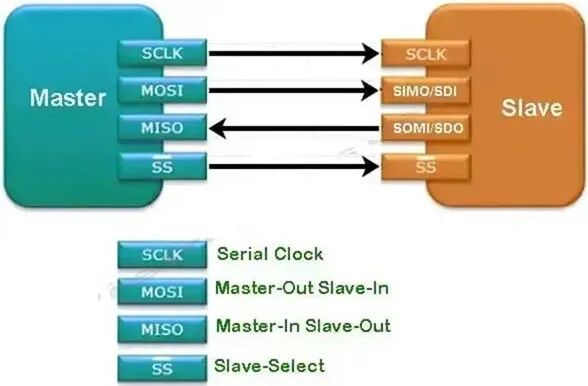
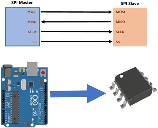
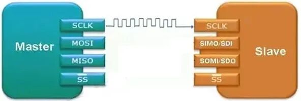
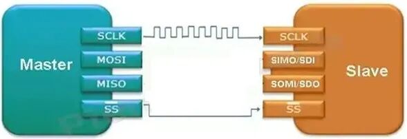
SPI bus is a communication interface that uses the SPI protocol to transfer data between devices, consisting of one master device and one or more slave devices connected together using four wires, as follows:
-
MOSI (Master Out Slave In).
-
MISO (Master In Slave Out).
-
SCK (Serial Clock).
-
SS/CS/CE (Slave Select/Chip Select/Chip Enable).
1) In the SPI protocol, MOSI
MOSI stands for Master Out Slave In, and the MOSI line transmits data from the master device to the slave device. In the SPI bus, the master device controls the communication and selects the slave device to communicate with by pulling the SS line low. The master device can then send data to the slave device using the MOSI line and receive data from the slave device using the MISO line.
The MOSI line is used to transmit data from the master device to the slave device. The slave device receives data on the MOSI line and processes it based on the commands and data sent by the master device. The MOSI line is an important part of the SPI communication protocol as it allows the master device to send data to the slave device and control the behavior of the slave device.
2) In the SPI protocol, MISO
MISO stands for Master In Slave Out, and the MISO line transmits data from the slave device to the master device. In the SPI bus, the master device controls the communication and selects the slave device to communicate with by pulling the SS line low. The master device can then send data to the slave device using the MOSI line and receive data from the slave device using the MISO line.
The MISO line is used to transmit data from the slave device to the master device. The master device receives data on the MISO line and processes it based on the commands and data sent by the slave device. The MISO line is an important part of the SPI communication protocol as it allows the slave device to send data back to the master device and respond to the master’s commands.
3) In the SPI protocol, SCK
SCK stands for Serial Clock, generated by the master device when the master device sends data on the MOSI line to the slave device, and the slave device receives data on the MISO line. The data transfer is synchronized using the SCK line to ensure data is received and transmitted at the correct time.
4) In the SPI protocol, CS / SS/CE
The chip select (CS) line, also known as the slave select (SS) line or chip enable, is used to select a specific slave device to communicate with the master device. In the SPI bus, the master device controls the communication and selects the slave device to communicate with by pulling the CS line low.
Each slave device on the SPI bus has its own CS line to select it for communication with the master device. The master device can communicate with multiple slave devices by sequentially selecting each slave and sending or receiving data through the MOSI and MISO lines, ensuring that data is only transmitted between the master device and the selected slave device.
#03Clock Polarity and Phase in the Serial Peripheral Interface (SPI) Protocol
The SPI protocol has several different types, defined by the way data is transferred between the master and slave devices. Here are 4 common types of SPI protocols:
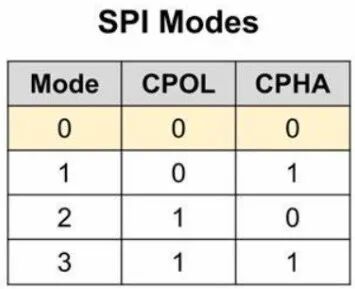
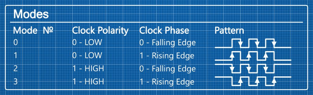
It can be seen that the timing rules for data sampling and output are defined based on the combination of clock polarity (CPOL) and clock phase (CPHA). The detailed description of these four operating modes is as follows:
-
Mode 0:CPOL = 0, CPHA = 0. The data sampling edge is the rising edge of the clock signal (data is sampled when the signal transitions from low to high), and the data output edge is the falling edge of the clock signal (data is output when the signal transitions from high to low). This mode is suitable for most standard SPI slave devices, with the clock idle at low level.
-
Mode 1:CPOL = 0, CPHA = 1. The data sampling edge is the falling edge of the clock signal (data is sampled when the signal transitions from high to low), and the data output edge is the rising edge of the clock signal (data is output when the signal transitions from low to high). This mode requires data to be prepared before the clock becomes valid and is suitable for high-speed modes.
-
Mode 2:CPOL = 1, CPHA = 0. The data sampling edge is the rising edge of the clock signal (note that the clock is idle at high level), and the data output edge is also the rising edge of the clock signal. This mode requires strict adherence to setup time requirements.
-
Mode 3:CPOL = 1, CPHA = 1. The data sampling edge is the falling edge of the clock signal (data is sampled when the signal transitions from high to low), and the data output edge is also the falling edge of the clock signal. This mode has the clock idle at high level and is suitable for certain special sensor interfaces.
Source: SPI – Serial Peripheral Interface | PiCockpit‘s
#04
Communication Architecture in the Serial Peripheral Interface (SPI) Protocol
Based on the characteristics of the SPI master-slave architecture, various communication architectures can be configured, such as single master-single slave, single master-multiple slaves, and multiple masters-multiple slaves. Here, we introduce the two most common communication architectures in automotive ECUs.
1) Single Master-Single Slave Architecture in the Serial Peripheral Interface (SPI) Protocol
In the single master-single slave interface of SPI, only one master device communicates with one slave device. The master device controls the timing and data transfer of the communication, while the slave device only responds to the commands and data sent by the master device.
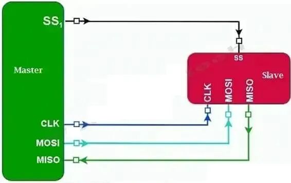
In this configuration, communication typically begins with the master device sending a clock signal to the slave device. The clock signal synchronizes the data transfer between the two devices. The master device also sends commands to the slave device, indicating what it should do. The slave device receives commands from the master device and responds with appropriate data. The master device then reads the data, and the communication is complete.
It is important to note that the SPI protocol does not define any specific format for the data being transmitted. Therefore, the data format to be transmitted between the two devices must be agreed upon by the master and slave device manufacturers.
2) Single Master-Multiple Slaves Architecture in the Serial Peripheral Interface (SPI)
In the single master-multiple slaves interface of the SPI protocol, there is one master device communicating with multiple slave devices. The master device controls the timing and data transfer of the communication and selects which slave device to communicate with at any given time.
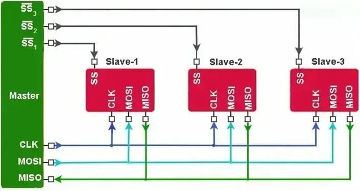
In this configuration, the master device sends a clock signal to all slave devices simultaneously. However, at any given time, only one slave device can communicate with the master device, while the other slave devices must remain inactive. To select the slave device to communicate with, the master device uses the CS signal. Each slave device has a separate CS signal used to enable or disable communication between the master device and that specific slave device. The master device can select the slave device to communicate with by activating its corresponding CS signal while deactivating the CS signals of the other slave devices.
Once the master device selects a slave device, it sends a command to that device indicating what it should do. The slave device receives commands from the master device and responds with appropriate data.
After communication with a specific slave device is complete, the master device can deactivate its CS signal and activate the CS signal of another slave device to communicate with it. The master device can communicate with all slave devices in a similar manner and switch between them as needed.
It is important to note that in the single master-multiple slaves architecture of SPI, all slave devices share the same clock signal and data lines. Therefore, it is crucial to ensure that the timing and data formats are compatible between all slave devices and the master device.
#05
Communication Process of the Serial Peripheral Interface (SPI) Protocol
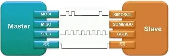
First, the hardware foundation for the SPI protocol is required, which includes a microcontroller or master device that supports the SPI protocol, one or more peripheral devices that support the SPI protocol, and four lines used to connect the master and slave devices:MOSI (Master Out Slave In), MISO (Master In Slave Out), SCK (Serial Clock), and SS (Slave Select).
Then, communication begins, and the specific communication process is described as follows:
1) Initialization (Step 1): The master device initializes the SPI communication by setting the necessary configuration parameters, such as clock frequency, data order (MSB or LSB priority), and clock polarity (CPOL) and phase (CPHA). The SPI protocol also allows for various configuration options, but it is important to set these options in the same way for both the master and slave devices to ensure correct communication as described in the configuration phase above.
2) Slave Selection (Step 2): The master device selects the slave device to communicate with by setting the corresponding slave select (SS) line to low.
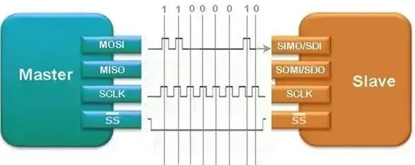
3) Data Transfer (Step 3): The master device sends data out through the MOSI line while receiving data from the MISO line, transferring data to the slave device. The clock signal generated by the master device determines the timing of the data transfer, and the slave device receives data on the MOSI line and sends back its response on the MISO line.
Data is transmitted in binary format, with each bit sent in order starting from the most significant bit. The number of bits transmitted is usually configurable, ranging from 4 bits to 16 bits or 32 bits.
4) Slave Deselect (Step 4): After the data transfer is complete, the master device deselects the slave device by setting the SS line back to high.
Once the data exchange is complete, the master device deactivates the CS signal, indicating to the slave device that the communication has ended. The master device can repeat steps 2-4 to communicate with other slave devices on the same SPI bus.
#06
Applications of the Serial Peripheral Interface (SPI) Protocol
Using the SPI protocol for communication between microcontrollers and peripheral devices has several advantages:
-
Simplicity: The SPI protocol is relatively simple and easy to implement, making it an attractive choice for many applications.
-
Efficiency: The SPI protocol is a full-duplex protocol, meaning data can be sent and received simultaneously. This makes it an efficient protocol for transferring data between devices.
-
Versatility: The SPI protocol can be used with a variety of devices, including sensors, displays, and storage devices. It is also widely supported by microcontrollers and other electronic components.
-
High speed: The SPI protocol can operate at high speeds, making it suitable for applications that require fast data transfer.
-
Low cost: The SPI protocol only requires four wires for communication, making it a cost-effective solution for many applications.
With these advantages of the SPI protocol, it has become a simple, efficient, and versatile communication protocol, widely used in various applications in the following fields:
-
Industrial control: SPI is used in various industrial control applications, such as factory automation and process control.
-
Consumer electronics: SPI is used in many consumer electronic products, such as smartphones, tablets, and laptops, for communication with sensors, displays, and storage devices.
-
Automotive systems: SPI is used in various automotive applications, including engine control, infotainment systems, and advanced driver-assistance systems (ADAS).
-
Medical devices: SPI is used in medical devices, such as heart rate monitors and blood glucose meters, to communicate with sensors and other peripheral devices.
-
Internet of Things (IoT) devices: SPI is used in many IoT devices, such as smart home devices and wearable technology, to communicate with sensors and other peripheral devices.
-
Data storage: SPI is used in data storage devices, such as solid-state drives (SSD), to communicate with the main device.
Despite the many advantages and widespread applications of the SPI protocol, it also has some disadvantages that may make it less suitable for certain applications, such as:
-
Limited number of devices: The SPI protocol is limited to communication between a single master device and up to four slave devices, which may not be sufficient for applications that require communication with a large number of devices.
-
Complexity of multi-master systems: If a system requires multiple master devices, the SPI protocol can become complex and more difficult to implement.
-
Distance limitations: The SPI protocol is not designed for long-distance communication, as the length of the wires used for communication is limited.
-
Limited data transfer: The SPI protocol is limited to transmitting one byte of data at a time, which may not be sufficient for applications that require the transfer of large amounts of data.
-
Security issues: The SPI protocol does not have built-in security features, which may be a concern for applications that require secure communication.
Despite the limitations and disadvantages of the SPI protocol, its simplicity and efficiency make it an indispensable communication method in embedded systems and microcontroller applications. With proper hardware design and software optimization, the disadvantages of the SPI protocol can be overcome, fully leveraging its advantages to meet the needs of various application scenarios.