The three low-speed communication protocols IIC, SPI, and UART are widely used in our actual designs. Common communications between various ICs and between PCBs and external serial ports often utilize these protocols. Today, we will specifically share the similarities and differences among these three low-speed communication methods.
|
Communication Name |
SPI |
IIC |
UART |
|
Synchronization/Asynchronous Communication |
Synchronization |
Synchronization |
Asynchronous |
|
Transmission Rate |
MHz Level |
kHz Level |
kHz Level (generally slower than IIC) |
|
Number of Signal Lines |
CS, MISO, MOSI, CLK (most common four-wire system, also has three-wire system) |
SCL, SDA |
RX, TX, GND |
|
Topology |
One Master, Multiple Slaves |
One Master, Multiple Slaves (also supports multiple masters) |
One-to-One |
|
Voltage Levels |
Commonly 5V, 3.3V |
Commonly 5V, 3.3V |
Common: Positive level is 0, negative level is 1 (±15V levels) |
|
Need for Resistors |
SPI generally requires a small series resistor to prevent signal ringing |
Requires pull-up and pull-down, generally in K levels |
No need |
|
Operating Modes |
Four modes (based on different clock phases and polarities) |
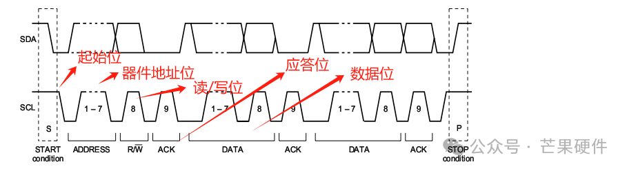
The I2C bus has three types of signals during data transmission: start signal, stop signal, and acknowledgment signal. |
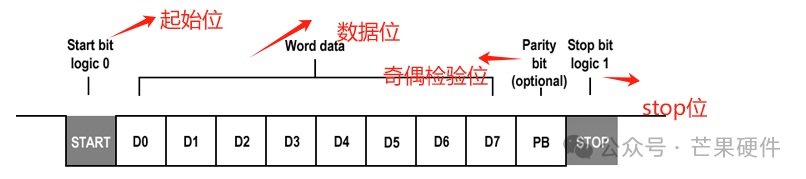
Each character generally consists of 10 bits (1 start bit, 7 data bits, 1 parity bit, 1 stop bit) |
IIC device timing explanation: Start bit: During the high level of SCL, SDA shows a falling edge; the next 7 bits are the device address. Following this is the read/write flag, which is 1 for read and 0 for write. After that is the acknowledgment bit (preparing for data bits), data bits, and stop bit: during the high level of SCL, SDA shows a rising edge.
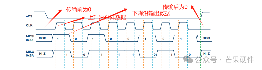
SPI timing explanation: The four operating modes of SPI are confirmed based on the polarity and phase of the clock. As shown in the figure below:
UART timing explanation: The UART timing consists of a start bit, data bits, parity bit, and stop bit. Each character consists of 10 bits.