In the modern technology field, embedded system interfaces play an indispensable role as the core hub for information exchange. Various interfaces achieve efficient data transmission and intelligent collaboration between devices through standardized communication protocols and specifications. As one of the core technologies in embedded development, a deep understanding and proficient use of interfaces directly determine the functionality and performance optimization of embedded systems. This article will take the SPI interface as a starting point, providing a detailed analysis of its working principles and technical characteristics, aiming to build a comprehensive knowledge system of interfaces for those eager to master embedded development.
1. Basic Concepts
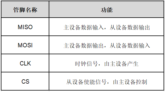
The full name of SPI is Serial Peripheral Interface. It is a high-speed, full-duplex, synchronous communication bus widely used in embedded systems for data transmission between controllers and various peripheral devices. The SPI interface features full-duplex communication, fast transmission speeds, and a simple protocol, making it suitable for many scenarios requiring efficient, short-distance communication. The SPI interface is often referred to as a 4-wire serial bus, operating in a master/slave mode, where the data transmission process is initialized by the master. The four lines are as follows:
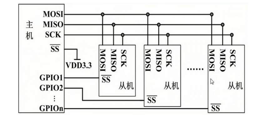
SPI operates in a master/slave mode, typically consisting of one master device (such as a microcontroller) and one or more slave devices.
During communication, the master device controls the slave devices, generating a clock signal that is provided to the slave devices via the SCK pin for synchronizing data transmission. The master sends data to the slave via the MOSI line while receiving data from the slave via the MISO line, allowing for bidirectional data transfer.
On the SPI bus, when one master communicates with multiple slaves, the master uses the SS signal to select a slave device for communication. Only the selected slave will respond to the master’s commands, while the other slaves remain unresponsive.
2. Operating Modes
SPI typically has four operating modes (0, 1, 2, 3), with the main differences being the settings of clock polarity (CPOL) and clock phase (CPHA), which determine when the clock signal transitions and when data is sampled.
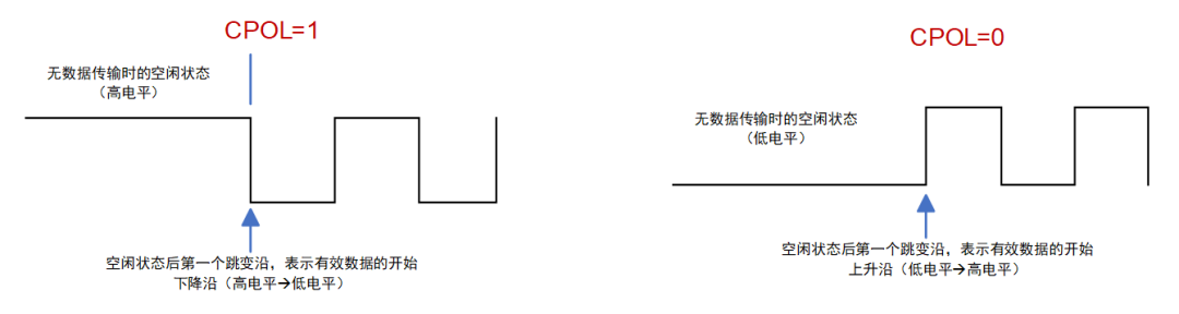
CPOL: Clock polarity; indicates whether the clock signal is high or low when idle.
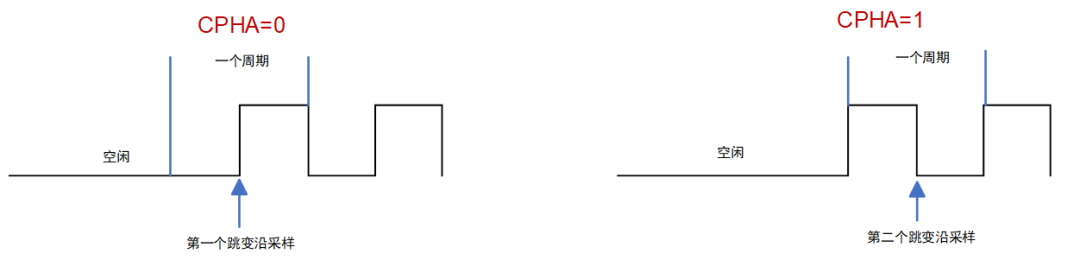
CPHA: Clock phase; indicates whether the SPI device samples data on the rising edge or the falling edge of the clock signal on the SCK pin. The edge on which the transition occurs depends on CPOL.
The master device generates corresponding clock pulses based on the data to be exchanged, forming the clock signal. The clock signal, controlled by clock polarity and clock phase, governs the verification of data exchange between the two SPI devices and when to sample the received data, ensuring that data is transmitted synchronously between the two devices. The clock phase and polarity of the SPI master device and the communicating slave device should match. The configuration of the master SPI clock and polarity should be determined by the peripheral device.
The different combinations of CPOL and CPHA create the four different modes of the SPI bus:
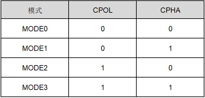
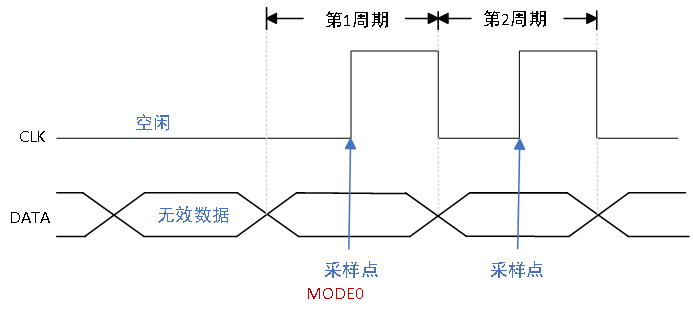
Mode 0 (CPOL=0, CPHA=0):
CPOL=0: Idle state is low, the first transition is a rising edge, and the second transition is a falling edge.
CPHA=0: Data is sampled on the first transition (rising edge).
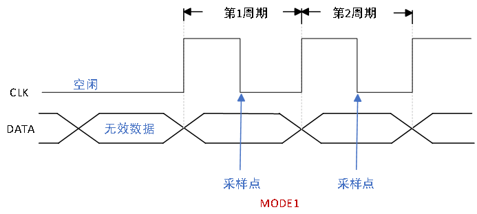
Mode 1 (CPOL=0, CPHA=1):
CPOL=0: Idle state is low, the first transition is a rising edge, and the second transition is a falling edge.
CPHA=1: Data is sampled on the second transition (falling edge).
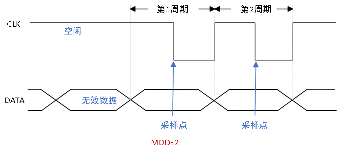
Mode 2 (CPOL=1; CPHA=0):
CPOL=1: Idle state is high, the first transition is a falling edge, and the second transition is a rising edge.
CPHA=0: Data is sampled on the first transition (falling edge).
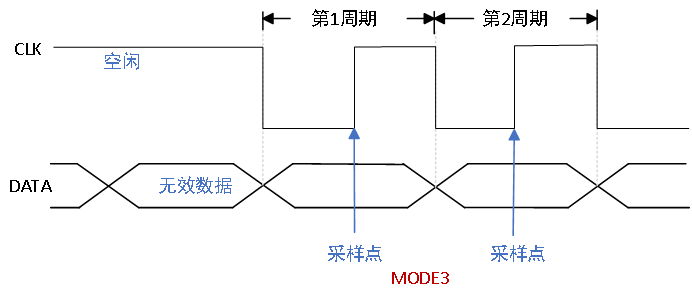
Mode 3 (CPOL=1; CPHA=1):
CPOL=1: Idle state is high, the first transition is a falling edge, and the second transition is a rising edge.
CPHA=1: Data is sampled on the second transition (rising edge).
This concludes the technical analysis of the SPI interface. We hope the above content provides actionable design ideas for embedded development learners and enthusiasts. If you encounter related challenges in your project practice, feel free to message us for further discussion.