Click the above  “Chuangxue Electronics” to follow and easily learn electronic knowledge.
Here are some issues encountered in mixed programming of C language and assembly language in Keil, written down for future reference.
1. Method to add assembly language modules in C language:
Example:
void func()
{
C language code……
#pragma asm
MOV R6,#23
DELAY2: MOV R7,#191
DELAY1: DJNZ R7,DELAY1
DJNZ R6,DELAY2
RET
#pragma endasm
C language code……
}
The red part is the C language part, and the green part is the embedded assembly language part. The assembly part needs to be wrapped with #pragma asm and #pragma endasm.
2. Solution to Keil’s “asm/endasm” error prompt
If you simply add assembly code like in 1, the compilation will report an error, as follows:
compiling sendata.c…
sendata.c(81): error C272: ‘asm/endasm’ requires src-control to be active
sendata.c(87): error C272: ‘asm/endasm’ requires src-control to be active
Target not created
The solution is as follows:
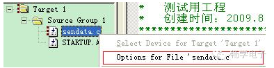
First, right-click on the C language file name that contains the assembly part, then select the option with the red box in the menu as shown above.
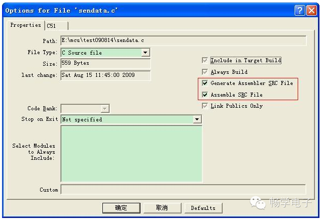
In the pop-up dialog, check the two items selected in the red box in the above image (by default, the check marks in front are gray, you need to make them black), and click OK.
3. Handling warnings related to ?C_START
After handling as described in 2, compiling again will not produce error messages, but the following warning messages will appear:
linking…
*** WARNING L1: UNRESOLVED EXTERNAL SYMBOL
SYMBOL: ?C_START
MODULE: STARTUP.obj (?C_STARTUP)
*** WARNING L2: REFERENCE MADE TO UNRESOLVED EXTERNAL
SYMBOL: ?C_START
MODULE: STARTUP.obj (?C_STARTUP)
ADDRESS: 000DH
The handling method is as follows:
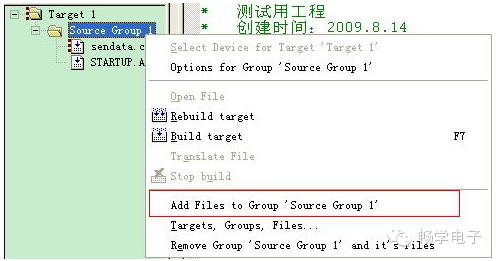
Right-click on the “Source Group 1” shown in the above image, and select “Add Files to Group ‘Source Group 1′” from the menu.
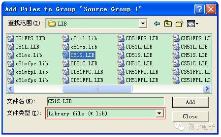
Find your KEIL installation directory, select the “LIB” directory under the “C51” directory, and choose the “C51S.LIB” file, click Add, then Close.
Note that the file selection box shown in the above image only displays .c files by default. You need to select “Library file (*.lib)” in the “File Type” to display LIB files.
After adding C51S.LIB to the project, compile again, and the warning messages will disappear.
linking…
Program Size: data=9.0 xdata=0 code=28
creating hex file from “sendata”…
“sendata” – 0 Error(s), 0 Warning(s).
4. Solution to register conflict issues
Assembly program blocks often use the general registers of the 51 microcontroller, such as R0-R7. In this case, there may be conflicts with R0-R7 that have already been used in the C language program, leading to some very subtle and bizarre errors. Although some say that KEIL can automatically allocate register groups to avoid conflicts, I still encountered conflicts during specific tests (or is there a problem with my KEIL settings?). Below is a test program:
/*************************************************************
* Test Program
*************************************************************/
#include
#include
typedef unsigned char uint8;
uint8 buf[16] =
{
0x55
};
uint8 i = 0;
/************************************************************
* Initialize microcontroller related registers
***********************************************************/
void UartInit()
{
SCON = 0x50;
TMOD |= 0x21;
PCON |= 0x80;
TH1 = 0xE8;
TL1 = 0xE8;
IE |= 0x90;
TR1 = 1;
}
/**************************************************
* Delay
***************************************************/
void delay()
{
#pragma asm
MOV R6,#19
DELAY2: MOV R7,#18
DELAY1: DJNZ R7,DELAY1
DJNZ R6,DELAY2
RET
#pragma endasm
}
/**********************************************
* Send a character to COM1
**********************************************/
void SendChar(uint8 byteToSend)
{
SBUF = byteToSend;
while(!TI);
TI = 0;
}
/************************************************************
* Read a byte
***********************************************************/
uint8 read_byte()
{
uint8 recvdata = 8;
delay();// Delay
return recvdata;
}
/**************************************************
* Main Program
***************************************************/
int main()
{
UartInit();// Serial port initialization
while(1)
{
buf[i++] = read_byte();
}
}
/**************************************************
* Serial Port Interrupt Handling
***************************************************/
void chuankou() interrupt 4
{
if(RI)
for(i=0; i < sizeof(buf); i++)
{
SendChar(buf);
}
RI = 0;
}
The program itself is very simple and straightforward. The main function continuously reads the return value of read_byte() into buf, and when there is a serial port interrupt, it outputs the content of buf to the serial port. The read_byte() function has also been simplified to return a fixed value of 8.
When this program is compiled and run in KEIL, a strange situation arises: the content of buf output to the serial port is always 0 (the output should naturally be 8).
Commenting out the delay(); line makes the program output correctly.
delay(); only serves as a delay, how could it change the function’s return value?
Let’s take a look at the assembly code generated for the read_byte() function.
USING 0
MOV R7,#08H
ACALL delay
RET
It turns out that the read_byte() function places the return value in R7, then calls the delay function, and then returns. The subsequent program calls the return value of read_byte() directly from R7.
However, during the “ACALL delay” call, R7, which already held #08H, was decremented to 0 during the delay, which is why the content of buf is all 0.
Knowing the reason makes it easier to handle. As I am a novice with limited microcontroller knowledge, I currently have thought of the following four solutions:
(1) Avoid using Rn already used in the C language part
When compiling the assembly module, check the assembly code generated by the C language part and avoid using those Rn that have already been used in the C language part and may cause conflicts in the assembly part. For example, in the delay program above, replacing R6 and R7 with R3 and R4 makes the program work correctly.
(2) Use the USINg X + ARX method to call other groups of Rn registers
The 51 microcontroller has 4 groups of R0-R7 registers, and it is said that the group generally used in main is the 0 group. Therefore, using other groups in the assembly part is fine. The content of the delay function can be modified as follows:
void delay()
{
#pragma asm
USING 2
MOV AR6,#19
DELAY2: MOV AR7,#18
DELAY1: DJNZ AR7,DELAY1
DJNZ AR6,DELAY2
RET
#pragma endasm
}
However, note that if used this way, the length of the delay may need to be recalculated. Because AR6 and R6 are different, the following two English descriptions were found online:
R0–R7 The eight 8-bit general-purpose 8051 registers in the currently active register bank.
A Maximum of four register banks are available.
AR0–AR7 Represent the absolute data addresses of R0 through R7 in the current register bank.
The absolute address for these registers changes depending on which register bank is currently selected.
These symbols are only available when the USING assembler statement is given.
Refer to the USING assembler statement for more information on selecting the register bank.
These representations are suppressed by the NOAREGS directive of the Cx51 compiler.
This means that R0–R7 are registers, while AR0–AR7 are addresses, so the clock cycle counts for “MOV AR6,#19” and “MOV R6,#19” are different. When I was debugging a data acquisition program, I initially didn’t notice this issue, which is why the data collected using AR6 and R6 was different. It was only later that I realized that they had different delays (the clock cycle counts for each instruction of the 51 microcontroller can be found in many places online, so I won’t list them here).
(3) Use stack protection for registers used in the assembly part
Simply put, before using Rn in the assembly part, push their contents onto the stack, and after the delay loop ends, pop them back from the stack and reassign them.
For example, the delay program above can be modified as follows:
void delay()
{
#pragma asm
MOV A, R6
PUSH ACC
MOV A, R7
PUSH ACC
MOV R6, #19
DELAY2: MOV R7, #18
DELAY1: DJNZ R7, DELAY1
DJNZ R6, DELAY2
POP ACC
MOV R7, A
POP ACC
MOV R6, A
RET
#pragma endasm
}
(4) Use RS0 and RS1 to switch the register groups
In the 51 microcontroller, RS0 and RS1 are used to select which group of Rn to use, so by modifying the values of these two bits in the assembly program, you can switch register groups.
The delay function can be modified as follows:
void delay()
{
#pragma asm
SETB RS1
SETB RS0
MOV R6,#19
DELAY2: MOV R7,#18
DELAY1: DJNZ R7,DELAY1
DJNZ R6,DELAY2
CLR RS1
CLR RS0
RET
#pragma endasm
}
After entering the assembly part, select to use the third group of registers, and before exiting the assembly part, switch back to the previously used group (which is the 0 group in this program).
However, for more precise delays, methods (3) and (4) may have some slight effects, as they add some push/pop or set/clear statements. Therefore, if the delay accuracy is high, and using methods (3) or (4), the time spent on push/pop or set/clear statements should also be considered when calculating the delay loop count.
In addition to the above four methods, I have also tried the following methods, but they failed:
One is to add “using 2” after the void delay() function definition, making it:
void delay() using 2
{
…………………………..
}
Or add USINg 2 in the assembly, making it:
void delay()
{
#pragma asm
USING 2
…………………………..
#pragma endasm
}
But it seems that neither works…
> > > > > > > > > > > > > > > > > > > > > > > > > > > > > > > > > > > > > > > > > > > > > > > > > > > > > >