“A detailed explanation of the Serial Peripheral Interface and its communication applications with memory, displays, Wi-Fi modules, and SD cards.”
 In a previous article, I explored the astonishing convenience of interfacing modern OLED displays with bare-metal microcontrollers. My point is simple: in most embedded applications, using a complete Linux SoC platform (like Raspberry Pi) is not only redundant but can also lead to more unresolved issues.
Some may argue that the OLED module might be an exception. For instance, adding wireless connectivity or external flash memory modules to an MCU will inevitably increase engineering complexity.
While there is no universal answer, I believe that exercises related to OLED are more challenging than most. In scenarios where gigabit transmission rates are not required, embedded peripherals often use the Serial Peripheral Interface (SPI): this extremely simple full-duplex bus easily achieves transmission rates over 50 Mbps and typically avoids unusual designs like OLED memory sorting logic.
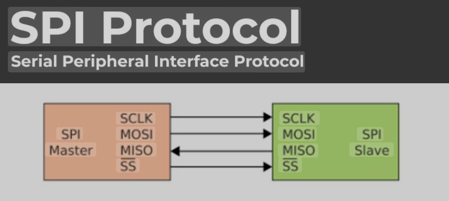
The basic principles and operation of SPI are easy to understand: the MCU leads the communication process. When data needs to be transmitted, the MCU pulls the corresponding peripheral’s “Chip Select” (CS-) pin low and outputs a clock signal on the bus SCK (Serial Clock) line. The MCU sends data bit by bit through MOSI (Master Out Slave In), while the peripheral responds in parallel through MISO (Master In Slave Out).
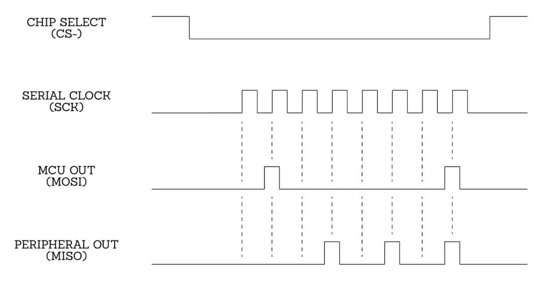 Key points of the commonly used (“Mode 0”) SPI protocol
The clock signal automatically stops after transmitting a single byte or its multiples. When the MCU needs to receive data unidirectionally, it can send a dummy byte via MOSI to activate the bus clock while reading MISO data; similarly, the peripheral can also use this mechanism to maintain communication synchronization.
Although providing hardware drivers for the SPI bus may not be absolutely necessary from a certain perspective, many microcontrollers still offer a hardware driver for the SPI bus. For example, the ATmega328P has an SPI data register (SPDR) with automatic send/receive functionality: when a byte is written to this register, the system automatically performs SPI bus transmission, and while sending data, this register will also be replaced by data from MISO (Master In Slave Out). When the transmission is complete, the microcontroller sets the “SPI Complete” (SPIF) flag in the SPI Status Register (SPSR).
Assuming I need to interface the ATmega328P with a 128kB SRAM module (model 23LC1024). This module has only 8 pins: 2 power pins (supporting 2.5-5.5V input), 4 basic SPI interface pins, and 2 redundant pins that do not need to be connected. For the specific connection, the module’s “Serial Input” (SI) pin should be connected to the MCU’s MOSI line, the “Serial Output” (SO) pin to the MISO line, and the SCK (clock) line should be interconnected. The final “Chip Select” (CS-) pin can be connected to any output line of the MCU; in this example, we will use bit 0 of port B.
After completing the hardware connection, the microcontroller needs to be configured: set the MOSI and SCK pins to output mode and MISO to input mode through the bit mapping of the DDRB register (as mentioned earlier). Then, activate two flags in the SPI Configuration Register (SPCR): “SPI Enable” (SPE) and “Master Mode” (MSTR):
DDRB = 0b11101111;SPCR = (1 << SPE) | (1 << MSTR);In addition to basic configuration, the SPCR register also supports bus rate prescaler settings (such as SPI2X, SPR1/SPR0 bits), but the default rate during the experimental phase (usually 1/4 of the system clock) is sufficient. After completing the register initialization, the following function can be used to achieve byte-wise bidirectional communication with the memory controller:
uint8_t spi_rxtx_byte(uint8_t val) { SPDR = val; while (!(SPSR & (1 << SPIF))); return SPDR;}The application layer protocol is also very simple, with the write process as follows:- Send the write command code 0x02
- Send 3 bytes of write address
- Continuously send the data stream to be written
- Pull the CS- pin high to end the operation
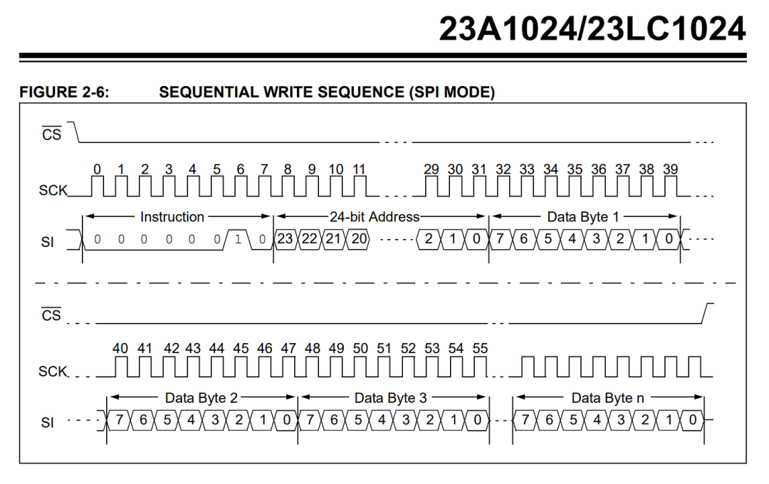
Although the chart may seem complex, the code to implement this functionality is simple and user-friendly:
void write_ext_ram_bytes(uint32_t addr, const uint8_t* ptr, uint16_t len) { PORTB &= ~1; /* CS- down */ spi_rxtx_byte(0x02); spi_rxtx_byte(addr >> 16); spi_rxtx_byte(addr >> 8); spi_rxtx_byte(ext_addr); while (len--) spi_rxtx_byte(*(ptr++)); PORTB |= 1; /* CS- up */}Reading from the memory works similarly; the MCU sends a “Read” command (0x03) and continuously sends dummy bytes while saving the responses received from the memory chip:
void read_ext_ram_bytes(uint32_t addr, uint8_t* ptr, uint16_t len) { PORTB &= ~1; /* -CS down */ spi_rxtx_byte(0x03); spi_rxtx_byte(addr >> 16); spi_rxtx_byte(addr >> 8); spi_rxtx_byte(addr); while (len--) *(ptr++) = spi_rxtx_byte(0); PORTB |= 1; /* -CS up */}Whether communicating with SRAM chips, interfacing with non-volatile flash memory controllers, driving SD storage cards, or operating low-cost Wi-Fi + TCP/IP modules from manufacturers like Espressif, the core interaction logic of the SPI bus protocol stack is highly unified.It is worth noting that the application layer protocols of current mainstream Wi-Fi modules actually reuse the command system of the 1980s Hayes modems (with moderate modernization). For example, developers can still initiate HTTP requests using the classic “AT” command set—this design, which deeply integrates retro command lines with modern IoT technology, can be considered a “retro tech Easter egg” in the embedded field.
The original text is reproduced from:https://lcamtuf.substack.com/p/mcu-land-part-2-mysteries-of-the, translated and verified
Note: If you want to receive KiCad content updates promptly, please click the business card below, follow, and set it as a star.
Common collection summary:
-
Learn KiCad with Dr. Peter
- KiCad 8 Exploration Collection
- KiCad Usage Experience Sharing
- KiCad Design Projects(Made with KiCad)
- Common Problems and Solutions
- KiCad Development Notes
- Plugin Applications
- Release Records