Hello everyone, welcome to <span>Lixin Embedded</span>.
In the field of industrial automation, Modbus is undoubtedly a name that cannot be ignored. As a communication protocol that originated in the late 1970s, it has stood the test of time, quietly supporting the interconnectivity of countless factories and devices. Today, let’s discuss Modbus, the veteran protocol of industrial communication.
The Historical Development of Modbus
In 1979, Modicon (the predecessor of Schneider Electric) introduced a communication protocol specifically designed for programmable logic controllers (PLCs), which is Modbus. At that time, communication between devices in industrial sites was still at a primitive stage, relying on voltage or current signals, such as using high and low levels to represent switch states, or using 0-10V and 4-20mA to transmit analog data. The emergence of Modbus was like equipping these devices with a translator, allowing PLCs and field devices to communicate more efficiently.
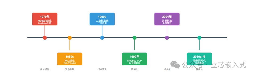
Modbus is the pioneer of Fieldbus protocols. What is a Fieldbus? In simple terms, it is a communication method for industrial networks that allows multiple devices to connect to a controller via a pair of cables, eliminating the hassle of point-to-point wiring. In the past, adding a sensor required pulling a new wire, leading to wiring costs and complexity resembling a spider web, while Fieldbus is somewhat like WiFi, connecting devices to a single network, saving time and effort.
In addition to Modbus, there are many other Fieldbus protocols in the industrial sector, such as Profibus, DeviceNet, and ControlNet, but Modbus has become one of the most widely used industrial protocols due to its simplicity, ease of use, and open-source nature, still being prevalent in factories worldwide today.
Modbus Design
The original intention of Modbus design was to facilitate smooth communication between PLCs and field devices. Initially, it operated over serial communication, such as RS-232 or RS-485, which was slow but stable. Later, with the development of network technology, Modbus was upgraded to support TCP/IP and Ethernet, adapting to the needs of modern industrial networks.
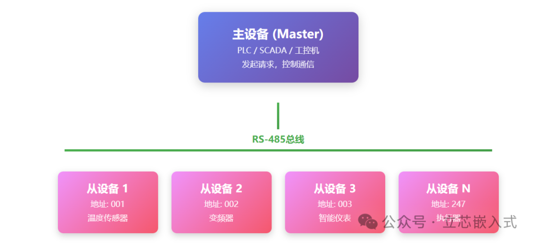
The core of Modbus is a master-slave communication model: a master device (Master) issues commands, while multiple slave devices (Slave) respond obediently. The master device can be a PLC, SCADA system, or an industrial computer, while slave devices may include sensors, frequency converters, or other intelligent instruments. The master device actively initiates requests, such as reading data or sending control commands, and the slave devices return data or execute operations based on the requests, making the entire process clear and straightforward.
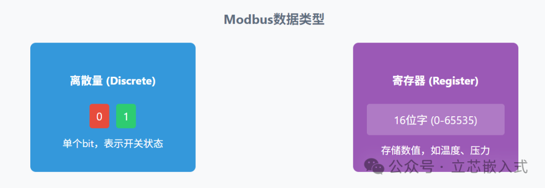
In terms of data, Modbus supports two basic formats:
- Discrete Inputs: which are single bits representing switch states, such as 0/1, true/false.
- Registers: 16-bit words, typically used to store values such as temperature, pressure, or other complex data that need to be expressed.
This simple data organization allows Modbus to handle both simple switch control and complex numerical transmission, making it highly adaptable.
Modbus Data Transmission
Modbus has its own rules for data transmission, and understanding these details is crucial for debugging and troubleshooting. Taking the most basic bit transmission as an example, Modbus sends bits in the least significant bit first (LSB to MSB) order. For instance, if a byte is 11010010, it will be transmitted as individual bits in the order of 0, 1, 0, 0, 1, 0, 1, 1.
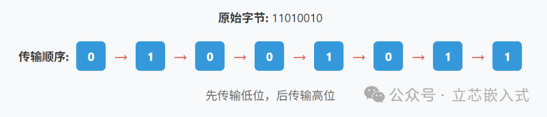
Why is this important? Because the receiving end must decode according to the same rules to ensure the data is not scrambled. This is similar to debugging a serial port where you need to confirm the baud rate, parity, and stop bits first; the bit order in Modbus is a similar basic convention.
As for byte transmission, Modbus will handle it differently based on the specific implementation (RTU, ASCII, or TCP), which we will discuss in detail later.
Addressing and Function Codes
Modbus communication relies on <span>addresses</span> and <span>function codes</span>, which act like the brain and instruction set of the command system.
Device Address
Each slave device has a unique address, typically ranging from 1 to 247. When the master device sends a request, it includes the target slave device’s address in the message to ensure the command reaches the correct device. This is similar to sending a package via courier; you need to clearly write the recipient’s address, or the package may end up in the wrong place.
Register Address

In Modbus, data is stored in different registers based on type, commonly including:
- Coils: starting from 00001, storing discrete values, both readable and writable.
- Discrete Inputs: starting from 10001, storing read-only discrete values.
- Input Registers: starting from 30001, storing read-only values.
- Holding Registers: starting from 40001, storing values that can be read and written.
By specifying the register address, the master device can accurately read and write target data. For example, to read the value of a temperature sensor, it may need to access input register 30001.
Function Code
The function code tells the slave device what to do.
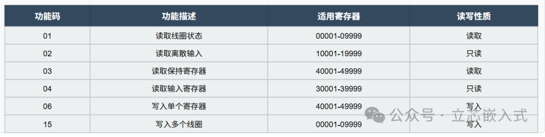
The message frame sent by the master device will include the device address, function code, and register address. Upon receiving this, the slave device will execute the corresponding operation based on the function code. This is similar to how a microcontroller in embedded development receives commands from a host computer, parses the command word, and then executes the corresponding action.
Three Implementations of Modbus
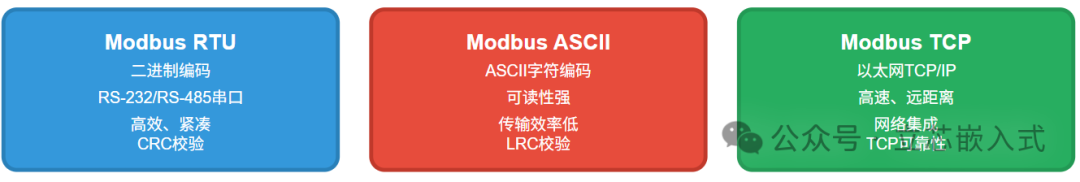
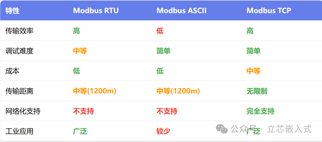
Modbus has three main implementations: RTU, ASCII, and TCP, each with its own characteristics and applicable scenarios.
Modbus RTU

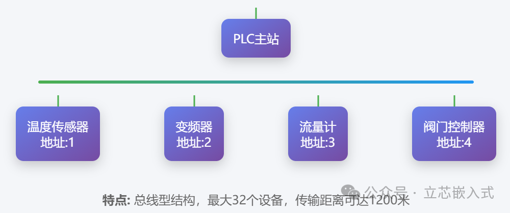
RTU (Remote Terminal Unit) is the classic implementation of Modbus, particularly suitable for serial communication, such as RS-232 or RS-485. RS-485 is especially common because it supports long-distance transmission (up to thousands of meters) and multipoint communication, with strong anti-interference capabilities, making it ideal for scenarios where devices are dispersed in factories.
RTU uses binary encoding, and the message frame is compact, containing the device address, function code, data, and CRC check. It is efficient and fast, but has strict timing requirements, so special attention must be paid to baud rate and frame intervals during debugging.
Modbus ASCII
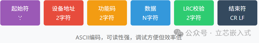
The ASCII mode uses readable ASCII characters (0-9, A-F) to represent data, with each byte split into two characters for transmission. For example, the binary data 0xAB would be represented as ASCII 41 42. The message frame starts with a colon (:) and ends with a carriage return and line feed, making it suitable for scenarios that require human-readable debugging.
However, the ASCII mode has longer messages and slower transmission speeds, making it far less efficient than RTU, and it is rarely used in actual industrial sites, mostly seen in older devices or educational contexts.
Modbus TCP: Embracing Ethernet
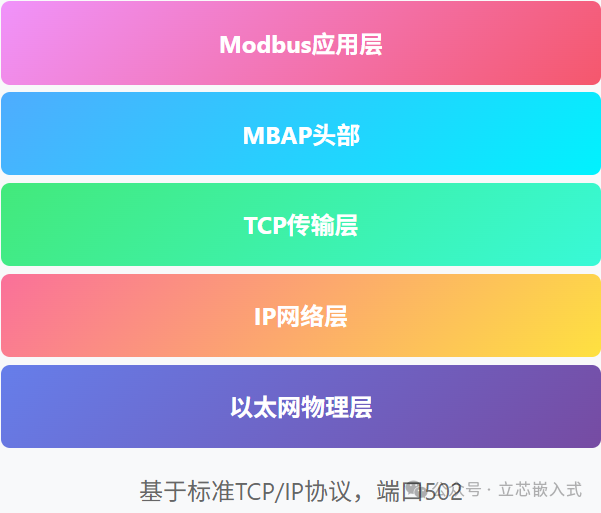
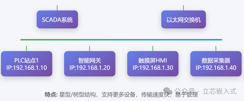
The TCP mode is the Ethernet version of Modbus, based on the TCP/IP protocol, running on standard Ethernet infrastructure. Compared to serial communication, TCP is faster, covers longer distances, and can easily connect to enterprise networks, making it particularly suitable for modern SCADA systems or remote monitoring.

The TCP message frame omits the CRC check (since the TCP protocol provides reliability guarantees) and adds an MBAP header (Modbus Application Protocol Header), which includes fields such as transaction identifier and protocol identifier. Many renewable energy projects, such as monitoring inverters in photovoltaic power plants, prefer using Modbus TCP for easy integration with cloud systems.
Why Modbus Succeeded
The success of Modbus is attributed to its simplicity and openness. The protocol design is straightforward, with a low learning curve, allowing engineers to easily implement it by simply browsing the documentation. Its open-source and free nature also means that manufacturers do not have to pay licensing fees, reducing costs. Many small and medium-sized factories have old equipment and limited budgets, but with Modbus, they can connect legacy devices to modern networks simply by using a serial-to-TCP gateway.
Of course, Modbus also has its shortcomings, such as low data throughput and less real-time performance compared to some modern protocols (like EtherCAT). However, in many scenarios, such as environmental monitoring and simple device control, its stability and ease of use are more than sufficient.
In the realm of industrial communication, Modbus may not be the fastest or the most advanced, but it is undoubtedly the most practical and reliable old friend.