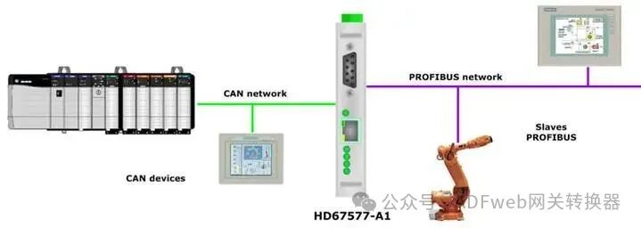
PROFIBUS Master toCAN-ADFWEB Gateway Converter–Guangzhou Xinyu IoT
Author:www.adfweb.com.cn Zou Wuyi Mobile185-020-77899 Email: [email protected]
1、Features:
The configurable “PROFIBUS Master/CAN converter” has the following features:
Triple isolation between CAN and PROFIBUS, CAN and power supply, PROFIBUS and power supply;
Can be mounted on a 35mm DIN rail;
Power supply: 8…24V AC or 12…35V DC;
Operating temperature range: -40°C to +85°C.
Configuration:
You need to install Compositor SW67577 software on your PC for the following configurations:
Define PROFIBUS parameters;
Define CAN bus parameters;
Define PROFIBUS network;
Define which CAN frames contain PROFIBUS information;
Define which PROFIBUS data is saved to CAN frames.
2、New Project / Open Project:
The “New Project” button creates a folder containing the entire device configuration.
Device configurations can also be imported or exported:
To clone a programmable “PROFIBUS Master / CAN converter’s configuration to configure another device in the same way, you need to keep the folder and all its contents;
To clone a project for a different version of that project, simply copy the project folder and rename it to a new name, then open the new folder using the “Open Project” button.
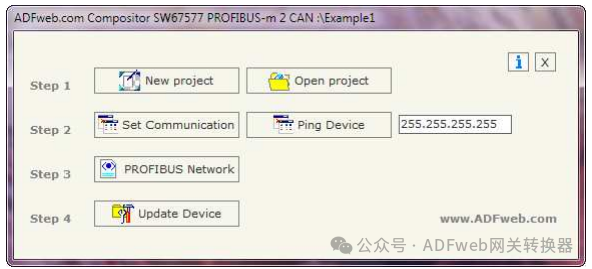
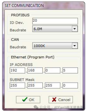
3、Communication Settings:
This section defines the basic communication parameters for the two buses (PROFIBUS and CAN).
Click the “Set Communication” button in the SW67577 main window (Figure 2), which will pop up the “Set Communication” window (Figure 3).
This window is divided into three sections: PROFIBUS section, CAN section, and the Ethernet section for programming.
PROFIBUS parameter field descriptions:
In the “ID Dev.” (Device ID) field, define the address for the PROFIBUS end;
In the “Baudrate” field, define the communication rate for the PROFIBUS end;
CAN parameter field descriptions:
In the “Baudrate” field, define the communication rate for CAN;
Ethernet (programming port) parameter field descriptions:
In the “IP ADDRESS” field, enter the IP address to be assigned to the device;
In the “SUBNET Mask” field, enter the subnet mask for the network where the device is located.
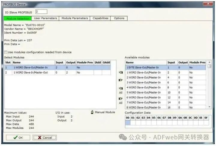
4、PROFIBUS Devices:
By clicking the “PROFIBUS network“ window (Figure 4), click the “Add Slave PROFIBUS” and “Modify Slave PROFIBUS” buttons (or double-click an existing PROFIBUS slave), which will pop up the “PROFIBUS Device“ window (Figure 6).
In this window, the following operations can be performed:
• Set the PROFIBUS slave ID (“PROFIBUS Slave ID”);
• Select the modules included in the PROFIBUS slave from the available modules in the GSD file (“Module Selection”);
• Modify the user parameters that exist for the PROFIBUS device (“User Parameters”);
• Modify the parameters of the selected modules (“Module Parameters”);
• View the capabilities and baud rates supported by the PROFIBUS device (“Capabilities”);
• Select data synchronization, freeze, and reset options (“Options”).