Hello everyone, I am Goat.I2C signals are a very common type of signal. It is a two-wire serial bidirectional bus used to connect microcontrollers and external devices. Because it only requires two pins (CLK and DATA), the hardware implementation is simple and highly scalable, making it widely used for communication between multiple integrated circuits ICs in a system.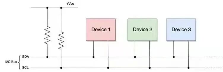
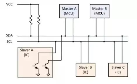
In terms of hardware connections, the implementation of the I2C protocol is divided into master and slave devices. One advantage of I2C over the SPI protocol is that it supports multiple masters or multiple slaves (SPI only supports one master and multiple slaves).
To assess the quality of I2C signals, it is essential to observe not only the signal quality but also the timing of the signals.
Common timing aspects to observe for I2C signals include:
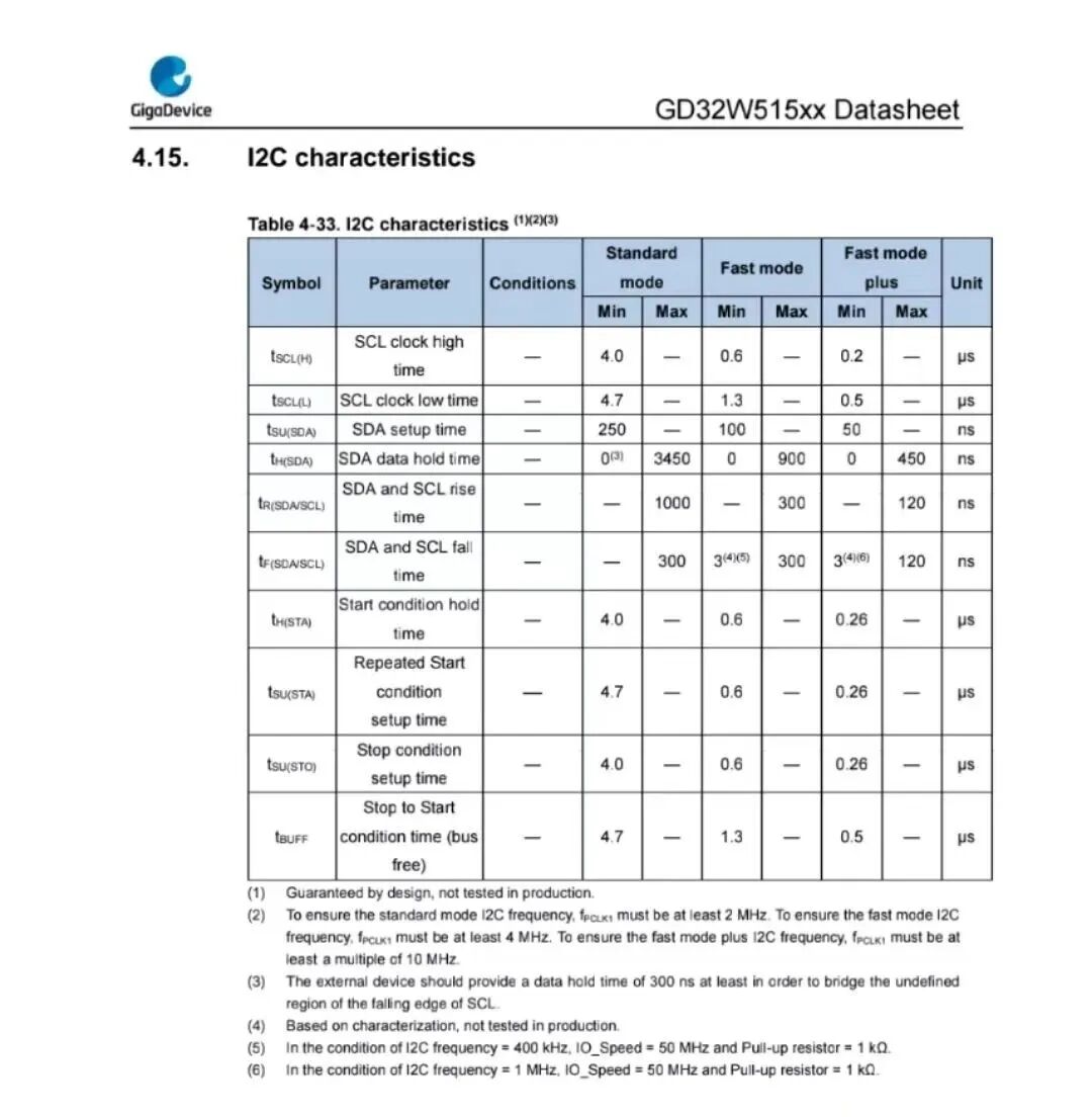
This timing includes clock signal frequency, setup time, hold time, SDA and SCL rise time, and other timing parameters. The specifications generally list the corresponding minimum and maximum times, and all these timings must fall within the specified range. Otherwise, I2C communication may encounter issues.
If signal quality issues are observed in I2C, they need to be addressed to prevent potential future problems. What are some common I2C signal issues? And how can we resolve them?
-
Overshoot
Overshoot is a very common issue. Whether it is due to power quality or signal quality, overshoot can occur. The main harm it causes is that it may impact the device. If the overshoot voltage is too high or lasts too long, it can damage the device. Additionally, it may create interference, causing crosstalk with other devices.
Such issues may not cause immediate effects, but over time they can lead to problems. Therefore, if overshoot issues are detected, they should be resolved during the design validation phase.
So, what causes I2C signal overshoot?

These reasons may need verification. It could be due to the device’s driving capability being too strong, improper matching, or crosstalk from adjacent signals on the board.
How to resolve it?
Based on the identified causes, appropriate solutions should be implemented. If the device’s driving capability is too strong, a device with suitable driving capability should be selected. If there is improper matching, a common practice is to add resistive matching or to place series resistors at the start or end to reduce overshoot. If crosstalk is the issue, it is necessary to avoid interference sources and coupling paths during PCB layout.
Previous Exciting Content:
Electronic Hardware Influencer Series – The Career Journey of a Huawei Hardware Expert with Over 20 Years of Experience (Part 3)
The Rich Guy of Capacitors – Tantalum Capacitors
Understanding QSPI Signal Protocol in Simple Terms (Part 2)
Can Hardware Engineers Find Jobs Right at Their Doorstep?
Click here👇, follow for more updates~
One-click triple connection: “Share”, “Like”, and “View”
Updates 2-4 times a week~