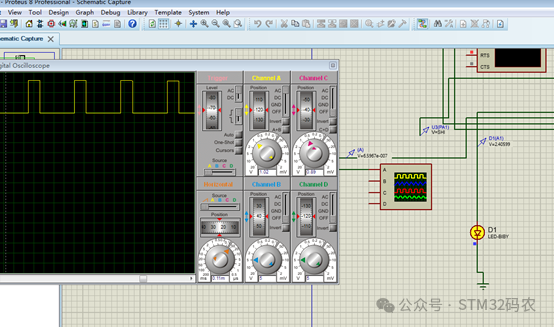
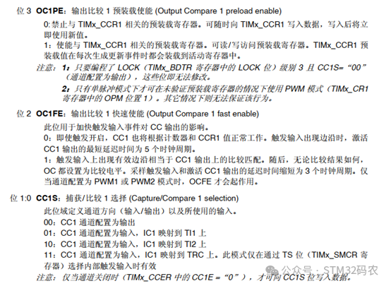
A PWM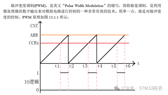 Here, there is a very important register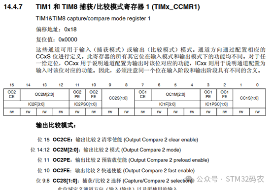
 2. Hardware Setup
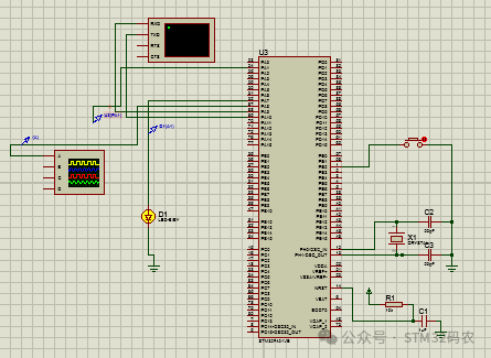 3. Software DevelopmentThe timer PWM configuration is slightly more complexThe configuration code is as follows
RCC_APB2PeriphClockCmd(RCC_APB2Periph_TIM1,ENABLE); // Enable TIM14 clock RCC_AHB1PeriphClockCmd(RCC_AHB1Periph_GPIOA,ENABLE); GPIO_InitStructure.GPIO_Pin= GPIO_Pin_8; // GPIOF9 GPIO_InitStructure.GPIO_Mode= GPIO_Mode_AF; // Alternate function GPIO_InitStructure.GPIO_Speed= GPIO_Speed_100MHz; // Speed 100MHz GPIO_InitStructure.GPIO_OType= GPIO_OType_PP; // Push-pull output GPIO_InitStructure.GPIO_PuPd= GPIO_PuPd_NOPULL; // No pull-up GPIO_Init(GPIOA,&GPIO_InitStructure); // Initialize PF9 GPIO_PinAFConfig(GPIOA,GPIO_PinSource8,GPIO_AF_TIM1);// GPIOF9 multiplexed to timer 14 // GPIO_PinAFConfig(GPIOA,GPIO_PinSource8, GPIO_AF_TIM1); TIM_TimeBaseStructure.TIM_Prescaler=84-1; // Timer prescaler TIM_TimeBaseStructure.TIM_CounterMode=TIM_CounterMode_Up;// Up counting mode TIM_TimeBaseStructure.TIM_Period=500-1; // Auto-reload value TIM_TimeBaseStructure.TIM_ClockDivision=TIM_CKD_DIV1; TIM_TimeBaseInit(TIM1,&TIM_TimeBaseStructure);// Initialize timer 1 TIM_OCInitStructure.TIM_OCMode =TIM_OCMode_PWM1; TIM_OCInitStructure.TIM_OutputState= TIM_OutputState_Enable; TIM_OCInitStructure.TIM_OCPolarity= TIM_OCPolarity_High; // TIM_OCInitStructure.TIM_OCIdleState= TIM_OCIdleState_Set; TIM_OCInitStructure.TIM_Pulse= 125; TIM_OC1Init(TIM1,&TIM_OCInitStructure); // TIM_OC1PreloadConfig(TIM1,TIM_OCPreload_Enable); // Enable TIM14 preload register on CCR1 TIM_ARRPreloadConfig(TIM1,ENABLE);// ARPE enable TIM_Cmd(TIM1,ENABLE); // Enable TIM14 TIM_CtrlPWMOutputs(TIM1,ENABLE);4. Test ResultsOpen PROTEUS, click run, and observe the waveform of PA8 on the oscilloscope