Click on the “Technical Training” above, and select “Pin to Public Account“
Over 160,000 industrial control professionals follow this WeChat platform: technical sharing, learning exchange, industrial control videos.
Many electricians are accustomed to using a shake table to measure the condition of motors in their daily work, which is undoubtedly a common and relatively safe testing method. Today, I will share how to use a multimeter to measure the condition of a motor, so that if a shake table is not available, you can still measure relevant conditions without delaying your work progress!
Measurement Method for Three-Phase Motors:
Set the digital multimeter to the 200Ω range and measure the three-phase power lines of the motor in pairs. If the resistance values from the three measurements are equal or very close, it indicates that the three-phase windings are well-connected.
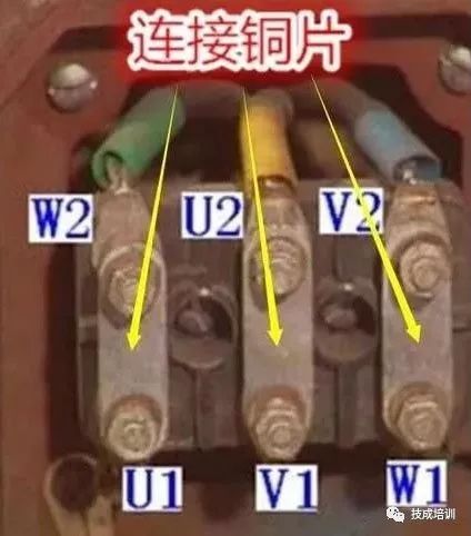
Next, open the motor’s junction box and remove the connecting copper pieces on the terminals, which disconnects the U, V, and W windings. Set the multimeter to the maximum resistance range and measure the resistance between any two ends of the U, V, and W windings. If the resistance values all show infinity, it indicates that the insulation between the motor phases is normal.
Finally, using the multimeter’s maximum resistance range, measure the resistance between any end of U, V, W and the motor casing. If the resistance values are all infinite, it indicates that the motor insulation is fine, and you can proceed to the power test for startup.
Measurement Method for Single-Phase Motors:
When measuring a single-phase motor, set the digital multimeter to the 2K range and first measure the resistance of the main winding, which is generally in the range of tens to hundreds of ohms, varying with the motor’s power.
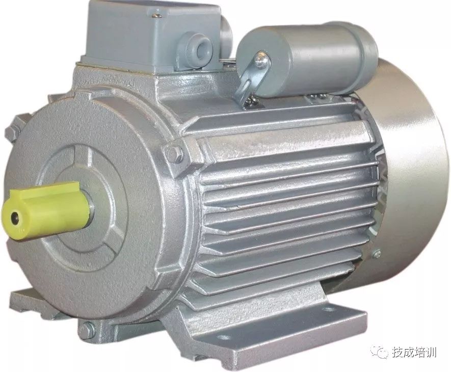
The resistance of the auxiliary winding is slightly larger than or equal to that of the main winding. If the resistances of the main and auxiliary windings are normal, measure the insulation between the main and auxiliary windings. Set the multimeter to the highest resistance range, and with the main and auxiliary windings disconnected, connect one probe to any terminal of the main winding and the other probe to any end of the auxiliary winding. An insulation resistance showing infinity is normal. Finally, measure the insulation resistance between the two windings and the casing, connecting one probe to the winding and the other to a conductive part of the motor casing. Showing infinity is normal.
This month’s selected outstanding articles:
Discover 59 Hidden Electrical Hazards Around You, with Pictures and Evidence!
Share with your friends and learn together!
Click Read the Original to learn about electrical work, PLC, variable frequency servo, CNC robots, and more.