Testing of the Contactors Using Multimeter Resistance Mode, The Testing Process is as Follows:
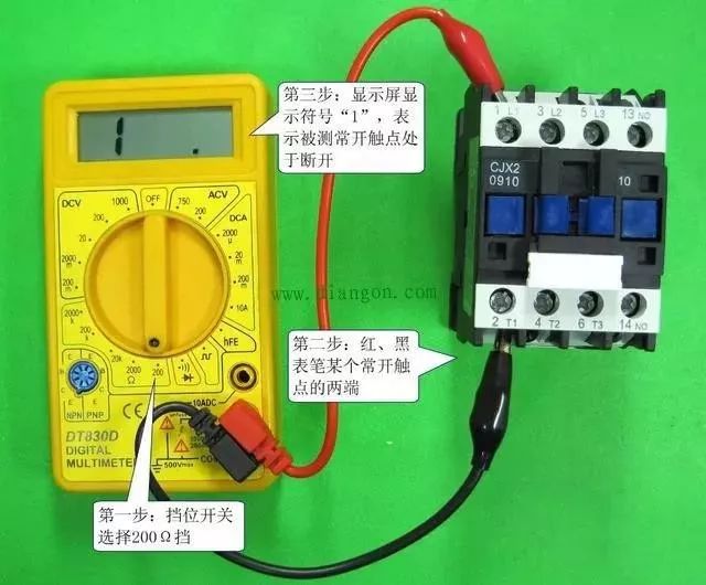
① In normal conditions, measure the resistance of the normally open and normally closed contacts. The image below shows the resistance measurement of the normally open contact of the AC contactor in normal conditions. Since the normally open contact is open in normal conditions, the normal resistance should be infinite. A digital multimeter will display the out-of-range symbol “1” or “OL” when measuring. When measuring the resistance of the normally closed contact in normal conditions, the normal measured resistance should be close to 0Ω. For AC contactors with a linkage frame, pressing the linkage frame will close the normally open contacts and open the normally closed contacts. You can use a multimeter to check if this is functioning correctly.
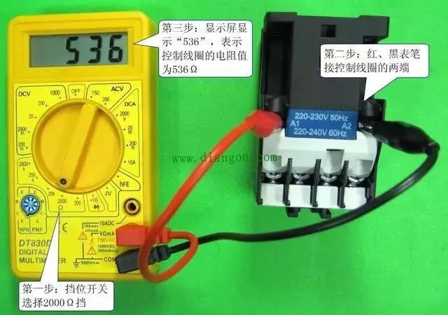
② Measure the resistance of the control coil. The measurement of the control coil’s resistance is shown in the image below. The normal resistance value of the control coil should be in the hundreds of ohms. Generally, the larger the power of the AC contactor, the greater the required pulling force of the coil on the contacts (i.e., the larger the current flowing through the coil), resulting in a lower coil resistance. If the coil’s resistance is infinite, it indicates an open circuit, while a resistance of 0 indicates a short circuit.
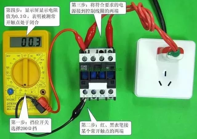
③ Power the control coil to test the resistance of the normally open and normally closed contacts. The image below shows the measurement of the normally open contact’s resistance when the control coil of the AC contactor is powered. When the control coil is powered, if the AC contactor is functioning correctly, it will emit a “click” sound, while the normally open contact will close and the normally closed contact will open. Therefore, the measured resistance of the normally open contact should be close to 0Ω, and the normally closed contact should be infinite (the digital multimeter will display the out-of-range symbol “1” or “OL”). If there is no change in the measured contact resistance before and after powering the control coil, it may indicate that the control coil is damaged or the transmission mechanism is stuck, etc.
Source: Internet