
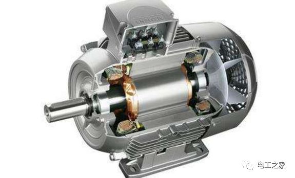
1. Quick Methods to Determine Motor Condition:
1. Use a multimeter to measure the DC resistance of the motor’s three-phase windings. The closer the results of the three measurements are, the better. A resistance difference within 2% is acceptable. If the difference exceeds 10%, the winding with the lower resistance may have an inter-turn short circuit.
2. Use a 500V insulation resistance tester to measure the insulation resistance between the three-phase windings and the ground (to the casing). For motors that have been stored for a long time, the insulation resistance should be above 0.5 megaohms to be considered good. A reading above 0.1 megaohms but below 0.5 megaohms indicates that the motor is damp and should be dried before use. Very low insulation resistance indicates that the insulation is damaged.
3. Rotate the motor rotor; it should turn smoothly without noise or friction, indicating that the bearings and air gap are normal.
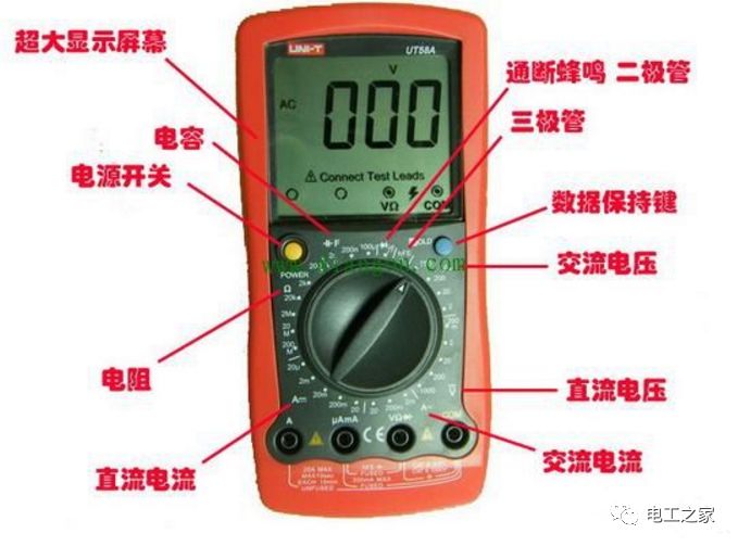
2. Testing the Motor with a Multimeter
1. Ground resistance (using the high range of the ohm setting): The insulation resistance between the motor winding (three-phase) and the casing should generally exceed 2M. In humid or acidic environments, the requirements can be lowered appropriately, but should not be below 0.5M.
2. Inter-phase resistance (using the high range of the ohm setting): The insulation resistance between different phase windings should generally exceed 2M. In humid or acidic environments, requirements can be lowered appropriately, but should not be below 0.5M.
3. Three-phase resistance (using the low range of the ohm setting): The resistance of the three-phase windings themselves should be approximately balanced (accurate data can be obtained using a digital multimeter; different motor capacities have different requirements, generally not exceeding 2%).
3. How to Check the Condition of a Motor?
1. Use an insulation tester, a 500V tester is sufficient, and measure the insulation resistance from the three terminals to the motor casing; it should be above 0.5M to indicate no short circuit to ground.
2. Measure the resistance between phases A/B/C; they should be approximately equal. A significant difference may allow the motor to turn but will reduce its lifespan. Remember, the larger the motor, the smaller the resistance! However, all three phases cannot be 0 ohms unless it is a very large motor (over 50KW). Note that for variable speed motors, the resistance of the six terminals may differ!
3. Check the bearings and fan; generally, when wrapping a motor, replace all components! Sometimes a seized bearing can burn out the motor!
4. The no-load current of the motor is generally 10%-50% of the rated current; sometimes the no-load current can even be zero!
5. When the motor operates at its rated current, it runs at full load, and the output power is basically 100%. If the operating current is low, it indicates that the motor’s output power is reduced and is running under light load.
6. If there is no three-phase power, find a washing machine’s starting capacitor; it can also run on 220V!
4. How to Test the Condition of a Single-Phase Motor?
Use a 500V megohmmeter to measure the insulation resistance between the motor winding and the casing; it should not be less than 0.5 megaohms. Use a multimeter to check for continuity in the winding leads; if all requirements are met, the motor is good.
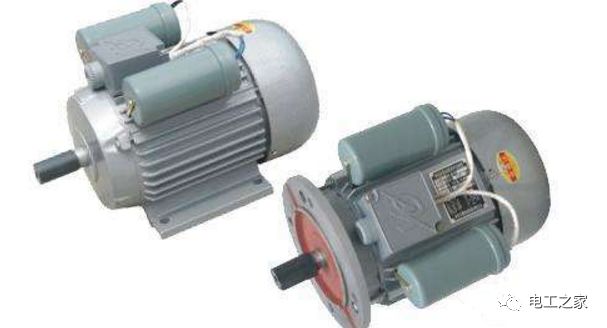
To test the condition of capacitors, a pointer multimeter is more convenient (there are also digital multimeters with a capacitance setting for direct measurement). Set the multimeter to the 1K or 10K resistance range, measure the two leads of the capacitor, and if the needle quickly deflects to the right and slowly returns to the left, the capacitor is good; if it remains deflected to the right, the capacitor is shorted; if the needle does not move, the capacitor is internally broken or has no capacitance. This method can only determine the capacitor’s condition; the size of the capacitance requires long-term experience to estimate.
5. How to Test the Condition of a Ventilation Fan Motor?
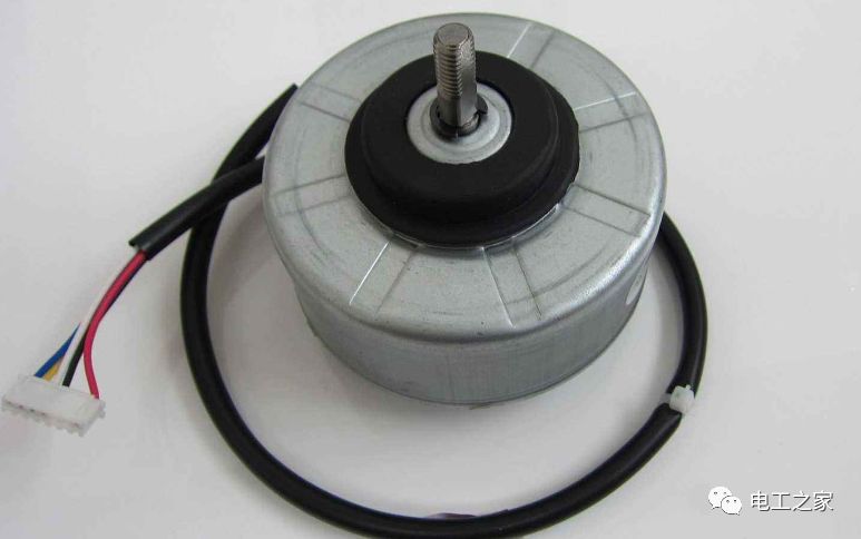
With a multimeter, use the resistance setting (X10) to measure the three wires of the motor; they should be interconnected, albeit with different resistance values. The resistance between red (connected to the live wire) and black (connected to the neutral wire) + blue (connected to the capacitor) and black should be greater than the resistance between red and black. Generally, it is possible that red and blue are connected (with resistance), while black is not connected to either red or blue, indicating that the internal overheat protection of the motor has burned out. If you have a replacement, change it; if not, just skip it.
6. How to Test the Condition of a Lathe Dual-Speed Motor?
1) Measure the three-phase resistance value when connected in a triangle (measure U1, V1, W1); the three-phase resistance values should be the same.
2) Measure the three-phase resistance value when connected in a star (measure U2, V2, W2, with U1, V1, W1 shorted); the three-phase resistance values should be the same.
3) The insulation resistance of the motor windings to ground should be greater than 5 megaohms.
7. How to Test the Condition of an Air Conditioner Fan Motor?
The motor has three wires, two sets of coils; one set is the starting coil, and the other is the running coil. The wire connected to the capacitor is the starting coil, and its resistance should be slightly higher than that of the running coil. Both sets of coils should have resistance values measured with a multimeter, approximately between 200 ohms and 400 ohms. 8. How to Test the Condition of Brushless Controllers for Electric Vehicles at 36V and 48V? Turn on the key switch; the 48V battery’s DC voltage is input to the controller through the key switch wire, passing through R3, R13, R4, etc., to the U6’s pin 3 for battery undervoltage detection, while another path goes to U13, U14, U15 to output +15V and +5V for powering the IC and final drive. The microcontroller PIC16F72’s pins 9 and 10 connect to a 16MHz crystal, pin 1 connects to R13 and C25 to form a reset circuit. After the key switch is unlocked, the microcontroller powers up and enters the initialization self-test state, primarily detecting:
1. The battery undervoltage detection circuit composed of R3, R73, R4, R11, C21, etc. (typical value: pin 3 of U6 input 3.8V).
2. The final current detection and overcurrent protection circuit composed of R5, R6, U1, etc. (normal value: pin 7 of U1 outputs 0V, pin 1 outputs about 3.6V).
3. The throttle reset signal (normal value: pin 6 of U6 inputs about 0.8V low level).
4. The brake reset signal (normal value: pin 7 of U6 inputs 4.8V high level).
5. The phase signal detected by the motor’s Hall element (normally at least one Hall wire inputs 4.1V, others 0V).
The status after self-testing is displayed by LED2, and here are the reference values (specific display depends on the microcontroller’s program design).
Flashing 1 stops 1—self-test passes normally
Flashing 2 stops 1—undervoltage
Flashing 3 stops 1—LM358 fault
Flashing 4 stops 1—motor Hall signal fault
Flashing 5 stops 1—lower tube fault
Flashing 6 stops 1—upper tube fault
Flashing 7 stops 1—overcurrent protection
Flashing 8 stops 1—brake protection
Flashing 9 stops 1—throttle ground wire disconnected
Flashing 10 stops 1—throttle signal and throttle power wire short circuit
Flashing 1 stops 11—throttle signal not reset when powered on
To test the condition of a DC motor, I can divide it into static testing and dynamic monitoring.
Static Testing:
1. Use a megohmmeter to measure insulation resistance (between armature and excitation; motor and excitation to casing);
2. Observe the commutator, it should be smooth and without scars;
3. Check the wear of the carbon brushes and whether the “pigtail” is loose or damaged;
4. Check whether the internal connections and output lead terminals are secure.
Dynamic Testing:
1. Determine the geometric centerline; symmetry judgment of the voltage applied in both forward and reverse directions;
2. If the no-load current exceeds 10%, there is a problem; the normal no-load current should be less than 10% to be considered normal;
3. Run the motor under no load to rated speed, cut off the power and let it coast to a stop, checking the operation of the motor’s drive system bearings and determining whether the dynamic balance meets the requirements. During the coasting process, the motor should not have significant vibrations or noise. First, check the excitation current and armature current; if they are not large, it can be determined that the motor coil is not damaged. Then check whether the mechanical part turns flexibly; if there are no issues, check the driver. 1. The higher the insulation resistance, the better. Generally, tens of megaohms are normal; however, in some humid southern regions, a few megaohms can still operate; in special cases, 500K to 1 megaohm can also operate, but it is not considered normal operation, rather it is to improve insulation resistance by baking the machine, which is low-voltage no-load operation. (This applies to low-voltage motors below 400V).
4. The dynamic balance test of the motor is generally determined by experience, using no-load, high speed, and then cutting off the power to coast. However, if dynamic balance correction is needed, it must be done using a professional dynamic balancing machine. There are many methods to test and adjust the geometric centerline of a DC motor, and there have been excellent descriptions in previous posts. It seems there are about 3 or 4 types. I generally use the method of checking whether the forward and reverse speeds are consistent under the same conditions to determine and adjust the position of the geometric centerline. At this time, the given speed should not be too high, about 10% of the rated speed.