1. Targeted Measurement Guidelines
1. Correct Use of the Multimeter
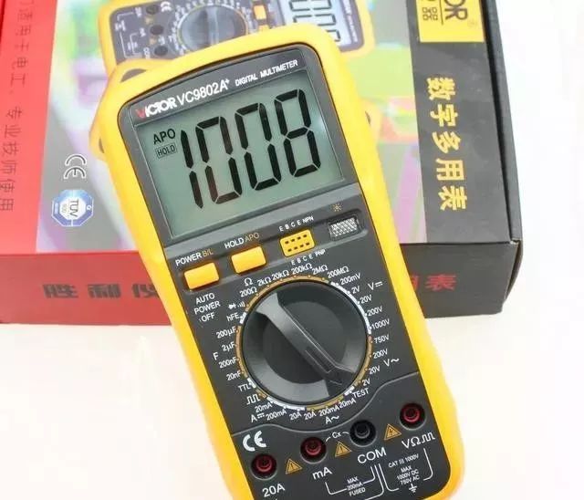
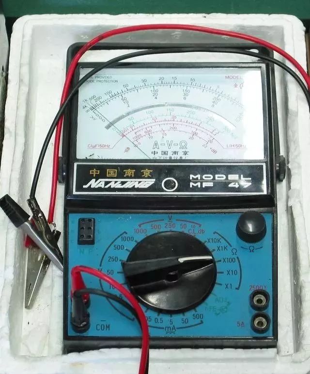
Correctly use the multimeter; familiarize yourself with the dial before use. Adjust the two zero position regulators gently. Properly select the terminals; insert the red and black probes into the correct holes.
Rotate the switch to the correct range; make sure the range is selected correctly. Choose the appropriate range for accurate measurement readings. Look at the scale line carefully; read the display accurately from a vertical view.
After measuring, switch the probes back; turn the switch to the high voltage range. Regularly check the internal battery; deterioration can cause electrolyte leakage. Use the instrument in a good environment; avoid vibrations and dampness, and ensure a weak magnetic field.
2. Correct Use of the Ohm Range on the Multimeter
To correctly use the ohm range, you should know and remember eight points. Ensure the battery voltage is sufficient, and the circuit being tested has no voltage. Select the appropriate multiplier range, and the needle should point to the middle of the scale.
Each time you change the multiplier range, you must readjust the resistance to zero. Ensure good contact at the probe tips; do not touch the probe ends with your hands. Measure the continuity of the circuit; use a range above one thousand ohms.
When testing diodes, different multipliers will yield different resistances. When measuring transformer windings, avoid contact with the hands as it may cause electric shock.
3. Precautions When Measuring Voltage with a Multimeter
When measuring voltage with a multimeter, there are eight precautions to remember. Understand the internal resistance of the meter, and ensure someone is monitoring. Connect the multimeter in parallel with the circuit being tested; do not change the range while powered.
When measuring DC voltage, clarify the positive and negative terminals of the circuit. When measuring the voltage across inductive circuits, do not disconnect the power during the test. For testing kilovolt high voltage, use dedicated test leads.
Induced voltage can vary significantly across different ranges.
4. Methods for Measuring DC Current with a Multimeter
To measure current with a multimeter, set the switch to the milliamp range, confirm the polarity of the circuit, and connect the meter in series with the circuit. Choose a larger range to minimize the impact on the circuit.
5. DC Method for Identifying the Ends of Stator Windings in Three-Phase Motors
For three-phase motor windings, use the DC method to identify the ends. Set the multimeter to the milliamp range, and use a DC power supply from a battery. Connect one winding to the meter and the other winding to the battery.
At the moment of energizing, if the needle moves, the positive terminal is the start. If it does not reverse, switch the connections; apply the same method to the remaining winding.
6. Residual Magnetism Method for Identifying the Ends of Stator Windings in Three-Phase Motors
For motors that have been operated, use the residual magnetism method to identify the ends. Mark the output terminals of the three-phase windings and connect them in parallel. Set the multimeter to the milliamp range, and connect the common point in parallel.
Slowly rotate the motor shaft while observing the meter needle. If the needle shows no significant movement, the three ends are connected. If the needle swings left and right, two ends are connected at one end.
Adjust one winding to switch ends, and use the same method to test until the needle stops moving, indicating that the ends are connected.
7. Loop Current Method for Identifying the Ends of Stator Windings in Three-Phase Motors
For motors that have been operated, use the loop current method to identify the ends. Connect the three-phase winding leads together in a triangle. Set the multimeter to the milliamp range, and connect in series with the three-phase windings.
Rotate the motor shaft evenly while observing the meter needle. If the needle shows minimal movement, the windings are connected at both ends. If the needle swings significantly, one winding is reversed.
The two connection points of the two leads are the start and end terminals.
8. Measuring the Speed of Three-Phase Motors with a Multimeter
To measure the speed of a three-phase motor, use the multimeter. Open the motor junction box and remove the connecting terminals. Set the multimeter to the milliamp range and connect across any phase winding.
Rotate the rotor for one complete turn and observe how many times the needle swings. For a two-pole motor, the needle swings once, indicating a synchronous speed of three thousand RPM. For a four-pole motor, the needle swings twice, indicating a synchronous speed of one thousand five hundred RPM.
Continue this method to determine the speed, which will be slightly lower than the synchronous speed.
9. Testing the Ground Resistance of Household Grounding Protection Lines
For household grounding lines, test the grounding resistance value. Set the multimeter to the voltage range, and connect the electric stove to the phase and neutral. Measure the voltage at the stove terminal to calculate the working current value.
Reconnect the stove to the neutral line, and measure the voltage at the stove terminal again. The difference between the two voltage readings, divided by the working current value, gives the grounding resistance value, with an error of about five percent.

10. Identifying Phase and Neutral Wires in Low Voltage AC Power Sources
For low voltage three-phase four-wire systems, identify the phase and neutral wires. Set the multimeter to the voltage range, with a range of 250V AC; connect one probe to the grounding point and touch the other probe to the power line.
If the needle deflects significantly, the probe touches the phase wire. If the needle barely moves, the probe touches the neutral wire.
11. Testing the Polarity and Functionality of Diodes
To test the polarity of a diode, set the multimeter to the kilo-ohm range. If the resistance is less than one kilo-ohm, the diode has forward resistance. Connect the black probe to the positive terminal and the red probe to the negative terminal.
If the resistance is several mega-ohms, the diode has reverse resistance. Connect the red probe to the positive terminal and the black probe to the negative terminal.
To determine if the diode is functioning, set the multimeter to the kilo-ohm range. A significant difference between forward and reverse resistance indicates good condition; the larger the value, the better. If the forward and reverse resistances are close, the diode has failed.
If both forward and reverse resistances are zero, the diode is shorted. If both resistances are infinite, the diode is open.
12. Checking the Functionality of High Voltage Silicon Rectifiers
To check the functionality of a silicon rectifier, set the multimeter to the voltage range. Connect the silicon rectifier in series with the multimeter and apply 220V AC. Set to 250V DC; connect the positive terminal of the rectifier.
If the reading is greater than thirty volts, the rectifier is functional; if the needle does not move, there is a fault. If the reading is 220V AC, it indicates a short circuit. If the reading is zero, the rectifier is open.
13. Testing the Functionality of Capacitors
To test the functionality of capacitors, use a microfarad capacitor tester. Set the multimeter to the kilo-ohm range and connect the probes to the two terminals. If the needle swings left and right, the greater the amplitude, the better the capacitor.
If the needle does not move, the capacitor is open. If the needle drops to zero and does not return, the capacitor has shorted.
14. Testing Electrolytic Capacitors with a Digital Multimeter in Buzzer Mode
To test the quality of electrolytic capacitors, use a digital multimeter in buzzer mode. Set the switch to buzzer mode and connect the probes to the positive and negative terminals. A short beep indicates the capacitor is functioning; if the tone stops, it shows the symbol.
If the buzzer sounds for a long time, the capacitor has a larger capacity. If the buzzer continuously sounds, the capacitor is shorted. If there is no sound, the capacitor is open.
15. Safety Regulations When Using Clamp Meters
When using a clamp meter, remember the safety regulations. Testing high voltage circuits must be done by two people. Ensure the potential of the wire being tested does not exceed the clamp meter’s voltage rating.
Always wear gloves and stand on an insulated platform. Maintain a safe distance from any live parts. When measuring low voltage bus currents, ensure insulation barriers are in place.
Do not use the clamp meter on wires with poor insulation or bare wires.
16. Correct Use of Clamp Meters
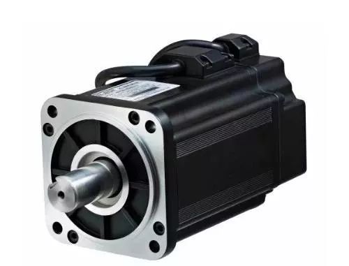
When using a clamp meter, select the appropriate model and specifications. Measure approximately using the maximum range, and select the appropriate range. Position the wire in the center of the clamp; ensure the moving and static cores are aligned well.
Once the wire is clamped, do not change the range while powered. Clamp meters for current and voltage must be measured separately. Do not insert both wires of a lighting circuit into the clamp at the same time.
After each test, set the range to the maximum setting.
17. Techniques for Measuring Three-Phase Three-Wire Current with Clamp Meters
When using a clamp meter to measure three-phase three-wire current, apply Kirchhoff’s laws to derive a measurement technique. Clamp one wire to read the current value of that phase.
Clamp two wires to read the current of the third phase. Clamp all three wires, and the balanced load will read zero.
18. Techniques for Measuring Small AC Current with Clamp Meters
When using a clamp meter to measure small AC currents, wrap the insulated wire around the core of the clamp. Divide the reading by the number of turns plus one to obtain the true current value.
19. Detecting Phase Loss in Three-Phase Resistance Furnaces
To detect phase loss in three-phase resistance furnaces, use a clamp meter. If the current value of two phase wires is less than the rated current and one phase wire has zero current, that phase’s heating element is burned out.
20. Locating Short Circuit Ground Faults in Low Voltage Distribution Lines
For long low voltage distribution lines, locating short circuit ground fault points can be difficult. If the faulty phase line is connected to an electric furnace, and the single control switch connects to the power supply, use a clamp meter to measure the current in sections along the line.
The point where there is a change in current indicates the short circuit ground fault point.
21. Testing Thyristor Rectifier Devices
To test thyristor rectifier devices, use a clamp meter. Clamp the anode connection wire and observe the current reading on the meter. If the meter indicates zero current, the device is not functioning.
For three-phase devices, if the current values are balanced, it is normal. If the current is significantly unbalanced, the phase shifts of the devices are inconsistent. If there are faults in the AC section, the rectifier transformer may be missing a phase.
22. Detecting User Phase Theft
If a user’s single-phase energy meter shows low or no reading, use a clamp meter to test before and after the energy meter. Clamp the phase and neutral wires; if the meter indicates a non-zero reading, there may be phase theft.
Measure both the phase and neutral wires; if there is a significant difference in current readings, it indicates phase theft, possibly in a one-phase to ground manner.
23. Safety Regulations When Measuring Insulation with Insulation Resistance Meters
When using insulation resistance meters, adhere to safety regulations. When measuring high voltage equipment, two people must be present. Ensure that the device being tested is fully powered down and properly discharged.
When measuring insulation on lines, obtain permission from the other party. Both circuits must be powered down, and measurements should not be taken during thunderstorms. When measuring near live equipment, ensure proper positioning of personnel.
Maintain a safe distance and ensure monitoring to prevent electric shock.
24. Correct Use of Insulation Resistance Meters
When using insulation resistance meters, select the appropriate voltage level. Ensure the device is fully powered down and properly discharged before testing. Clean the surface of the device to ensure it is free from dirt.
Ensure the meter is positioned properly, away from electric and magnetic fields. Place it horizontally without tilting, and conduct both open and short circuit tests. Use two-color single-core flexible leads that are well insulated and do not tangle.
Clearly identify the connection terminals and ensure correct connections. Rotate the handle clockwise, gradually reaching a constant speed. There is no fixed time for testing, and record the reading once the needle stabilizes.
25. Important Considerations When Using Insulation Resistance Meters
When using insulation resistance meters, remember eight important points. Do not touch the connection terminals with your hands during testing. Avoid cleaning the meter’s glass during the testing process.
When measuring insulation to ground, connect the grounding terminal to the outer casing. For capacitive large devices, disconnect from the rated speed. When testing electrolytic capacitors, connect the grounding terminal to the positive terminal.
For devices tested on the same platform, it is best to use the same meter. When testing insulation, note the temperature during measurement. Avoid testing resistances below one hundred kilo-ohms, and do not use the meter for continuity testing.
26. Connecting Diodes in Series to Prevent Discharge of the Device Under Test on Insulation Resistance Meters
Connect a diode in series with the insulation resistance meter. This prevents the device under test from discharging current during testing. This eliminates needle fluctuations and ensures accurate readings.
After testing, stop rotating to avoid damaging the meter.
27. Methods to Increase the Voltage of Insulation Resistance Meters
For low voltage insulation resistance meters, connect them in series to measure insulation. The voltage levels will add up, and the insulation resistance readings will combine.
28. Insulation Absorption Ratio of Power Transformers
To assess the quality of transformer insulation, use an insulation resistance meter. At approximately twenty degrees Celsius, begin timing from the moment of measurement: check the readings at fifteen seconds, and stabilize at elapsed seconds.
The ratio of two insulation resistances is called the insulation absorption ratio. A ratio greater than 1.3 is good, while less than 1.3 indicates moisture.
29. Rapid Assessment of Low Voltage Motors
To quickly assess low voltage motors, open the junction box for testing. Use an insulation resistance meter to measure the minimum insulation resistance value, which is eight mega-ohms at thirty-five degrees Celsius, reducing by half for every increase of ten degrees.
For every decrease of ten degrees, multiply by two. A reading exceeding this indicates the motor is good. Set the multimeter to the milliamp range and use the star connection method. Connect the probes to any two phase heads and slowly rotate the shaft.
If the needle swings significantly left and right, and the results are consistent over three tests, the motor is good; otherwise, it is not usable.
30. Testing High Voltage Silicon Rectifiers with Insulation Resistance Meters
To test the quality of high voltage silicon rectifiers, use an insulation resistance meter. Connect the grounding wires to the two leads, ensuring contact with the ends of the rectifier. Measure the resistance in both polarities; a significant difference indicates good condition.
If the two readings are very close, the rectifier has failed. If both readings are infinite, the rectifier is open. If both readings approach zero, the rectifier has a short circuit.
31. Testing the Quality of Self-Ballasted High-Pressure Mercury Lamps with Insulation Resistance Meters
To test the quality of high-pressure mercury lamps, use a kilovolt insulation resistance meter. Connect the grounding wires to the two leads and attach them to the lamp terminals. Place the mercury lamp in a dim environment and gradually increase the testing speed.
If the reading is less than half a mega-ohm, the lamp will glow. If the lamp does not light, the reading will be zero, indicating a short circuit inside the lamp. If the needle indicates infinity, there is an open circuit fault inside the lamp.
32. Testing the Quality of Fluorescent Tubes with Insulation Resistance Meters
To test the quality of fluorescent tubes, use a kilovolt insulation resistance meter. Set the multimeter to the voltage range, with a measurement range of 500V DC. Connect the multimeter in parallel, ensuring the polarities match.
Connect the grounding wires to the two ends of the lamp. If the lamp lights up at rated speed, it is normal if it does not exceed three hundred volts. If the lamp glows slightly, it indicates aging above three hundred volts.
If the lamp does not light at all, it indicates that the lamp has failed.
33. Testing the Quality of Starters for Fluorescent Lamps with Insulation Resistance Meters
To test the quality of starters for fluorescent lamps, use an insulation resistance meter. Connect the grounding wires to the two leads and attach them to the starter terminals. Slowly and gently rotate the meter’s handle; the neon bulb should discharge with a red flash.
If the starter is functioning, otherwise it is defective.