
How to Use a MultimeterA multimeter can measure direct current, direct voltage, alternating voltage, and resistance; some can also measure power, inductance, and capacitance, making it one of the most commonly used instruments by electricians.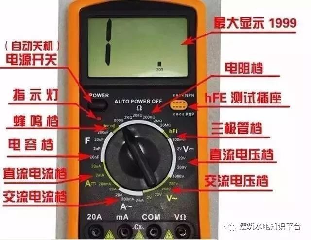 1. Basic Structure and Appearance of the MultimeterThe multimeter mainly consists of three parts: the indication part, the measurement circuit, and the switching device. The indication part is usually a magnetic electric micro-ammeter, commonly known as the meter head; the measurement part converts the measured electrical quantity into a small direct current suitable for the meter head, usually including shunt circuits, voltage divider circuits, and rectifier circuits; the measurement of different types of electrical quantities and the selection of ranges are achieved through the switching device.
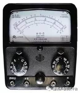 Model 500 Multimeter2. How to Use a Multimeter1. Correctly Select the Terminals (or Sockets)The red test lead should be connected to the red terminal (or the socket marked with a “+” sign), and the black test lead should be connected to the black terminal (or the socket marked with a “-” sign). Some multimeters have measurement terminals for AC and DC up to 2500 volts; when using, the black test lead should still be connected to the black terminal (or the “-” socket), while the red test lead should be connected to the 2500-volt terminal (or socket).
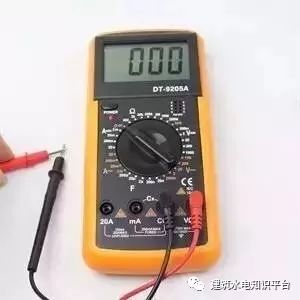 2. Correctly Select the Position of the SwitchRotate the switch to the required position based on the measurement object. For example, if measuring current, turn the switch to the corresponding current range; for voltage measurement, turn it to the corresponding voltage range. Some multimeters have two switches on the panel: one to select the measurement type and the other to select the measurement range. When using, first select the measurement type, then select the measurement range.3. Choose an Appropriate RangeBased on the approximate range of the measurement, turn the switch to the appropriate range for that type. When measuring voltage or current, it is best to keep the pointer within one-half to two-thirds of the range for more accurate readings.4. Correctly Read the ValuesThere are many scales on the dial of the multimeter, each suitable for different measurement objects. Therefore, when measuring, read the value on the corresponding scale while also paying attention to the scale reading and the range to avoid errors.5. Correct Use of the Ohm Range1. When measuring resistance, choose an appropriate multiplier range to ensure the pointer stops at a less dense part of the scale. The closer the pointer is to the middle of the scale, the more accurate the reading; the further left, the denser the scale lines, and the worse the accuracy. 2. Zero adjustment: Before measuring resistance, touch the two test leads together and rotate the “zero adjustment knob” until the pointer just points to the zero position on the ohm scale; this step is called zeroing the ohm range. This step must be repeated every time the ohm range is changed to ensure measurement accuracy. If the pointer cannot be adjusted to zero, it indicates that the battery voltage is insufficient and needs to be replaced. 3. Do not measure resistance while the circuit is powered. When measuring resistance, the multimeter is powered by a dry battery, and the resistance being measured must not be live to avoid damaging the meter head. During the use of the ohm range, do not short-circuit the two test leads to avoid wasting battery power.6. Pay Attention to Operational Safety1. When using the multimeter, avoid touching the metal parts of the test leads to ensure safety and measurement accuracy. 2. When measuring high voltage or large current, do not switch the dial while powered, as this may damage the switch. 3. After using the multimeter, it is best to turn the switch to the highest AC voltage range, as this is the safest for the multimeter to prevent damage due to oversight during the next measurement. 4. Before the test leads contact the measured circuit, conduct a thorough check to ensure all connections are correct.How to Use a MegohmmeterA megohmmeter, commonly known as a shake meter, is used to measure high resistance and insulation resistance, with its unit of measurement being megohms (MΩ), hence the name megohmmeter. There are many types of megohmmeters, but their functions are generally similar.
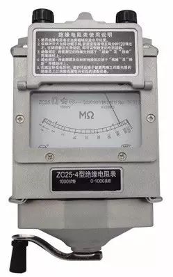 Hand-cranked Megohmmeter
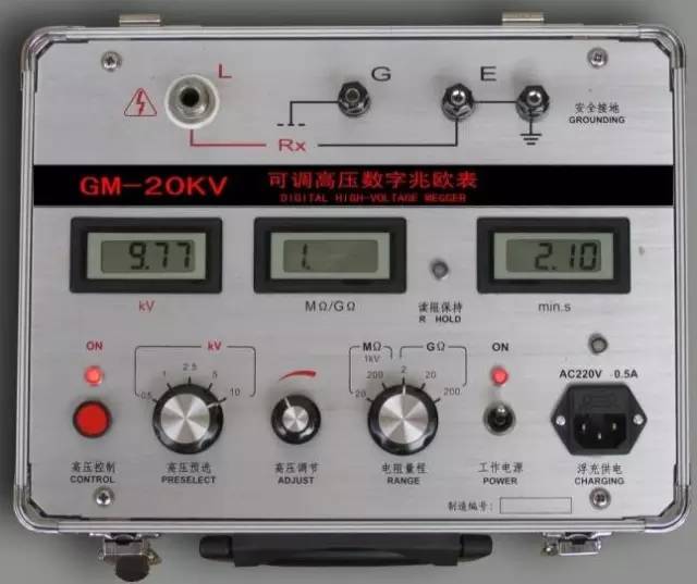
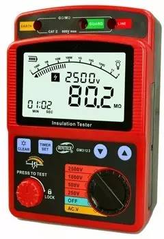 Electronic Megohmmeter1. Selection of MegohmmeterThe voltage rating of the megohmmeter should be higher than the insulation voltage rating of the object being measured. Therefore, when measuring the insulation resistance of equipment or circuits with a rated voltage below 500V, a 500V or 1000V megohmmeter can be used; when measuring insulation resistance of equipment or circuits with a rated voltage above 500V, a 1000~2500V megohmmeter should be selected; when measuring insulators, a 2500~5000V megohmmeter should be selected. Generally, when measuring insulation resistance of low-voltage electrical equipment, a megohmmeter with a range of 0~200MΩ can be used.2. Method for Measuring Insulation ResistanceA megohmmeter has three connection terminals, the two larger upper terminals are marked as “Ground” (E) and “Line” (L), and the smaller lower terminal is marked as “Protective Ring” (or “Shield”) (G).
 1. Insulation Resistance from Line to GroundConnect the “Ground” terminal of the megohmmeter (i.e., the E terminal) reliably to the ground (generally to a grounding body), and connect the “Line” terminal (i.e., the L terminal) to the measured line, as shown in the figure below.After connecting, rotate the megohmmeter clockwise, gradually accelerating to about 120 revolutions per minute, and maintain a steady speed. When the speed stabilizes, the pointer of the meter will also stabilize, and the value indicated by the pointer is the insulation resistance value of the measured object. In practice, the E and L terminals can also be connected arbitrarily, i.e., E can connect to the measured object, and L can connect to the grounding body (i.e., ground), but the G terminal must not be connected incorrectly.
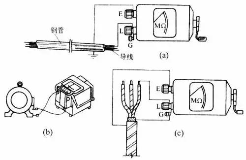 (a) Measuring the Insulation Resistance of a Line(b) Measuring the Insulation Resistance of a Motor(c) Measuring the Insulation Resistance of a Cable2. Measuring the Insulation Resistance of a MotorConnect the E terminal of the megohmmeter to the motor casing (i.e., ground), and connect the L terminal to one of the windings of the motor, as shown in the figure above; the measured insulation resistance value is the insulation resistance value of that winding to ground.3. Measuring the Insulation Resistance of a CableWhen measuring the insulation resistance between the conductive core of the cable and the cable casing, connect the E terminal to the cable casing, the L terminal to the core, and connect the G terminal to the insulation layer between the casing and the core, as shown in figure c.3. Usage Precautions(1) Before use, perform open circuit and short circuit tests. Keep the L and E terminals in the open state, shake the megohmmeter, and the pointer should point to “∞”; short-circuit the L and E terminals, slowly turn, and the pointer should point to “0”. If both conditions are met, the megohmmeter is good. (2) When measuring the insulation resistance of electrical equipment, the power must be cut off, and the equipment should be discharged to ensure personal safety and measurement accuracy. (3) The megohmmeter should be placed horizontally during measurement, and it should be pressed firmly to prevent shaking during operation; the shaking speed should be 120 revolutions per minute. (4) The connecting wires should be made of multi-strand soft wire and have good insulation properties; the two lead wires must not be twisted together to avoid inaccurate measurement data. (5) After measurement, the measured object should be discharged immediately; do not touch the measuring part of the measured object or remove the wires before the shaking handle of the meter has stopped turning and the measured object has been discharged to prevent electric shock.AmmeterAn ammeter is connected in series with the circuit being measured to measure its current value. Depending on the nature of the current measured, it can be divided into direct current ammeters, alternating current ammeters, and dual-purpose ammeters. Its measurement range can be further divided into microammeters, milliampere meters, and ampere meters. Based on the principle of operation, ammeters can be categorized into magnetic electric type, electromagnetic type, and electrodynamic type.
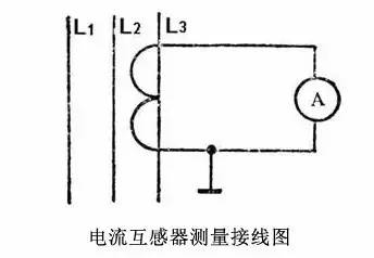
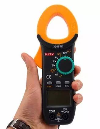 Portable Clamp Meter1. Selection of AmmeterWhen measuring direct current, the most common is to use a magnetic electric type instrument, but electromagnetic or electrodynamic instruments can also be used. For measuring alternating current, the electromagnetic type instrument is more commonly used, though the electrodynamic type can also be used. In situations where high accuracy and sensitivity are required, magnetic electric type instruments should be used; for situations where precision is not strictly required and the measured current is large, cost-effective electromagnetic type instruments are often chosen.The range of the ammeter should be determined based on the size of the current being measured, ensuring the measured current value falls within the ammeter’s range. If the size of the current is unclear, a larger range ammeter should be used for preliminary testing to avoid damage to the instrument from overload.2. Usage Methods and Precautions1. The ammeter must be connected in series with the circuit being measured.2. When measuring direct current, the ammeter’s terminals marked “+” and “-” must not be reversed, or the instrument may be damaged. Magnetic electric ammeters are generally only used for measuring direct current.3. Choose an appropriate range based on the size of the current being measured. For ammeters with two ranges, they have three terminals; during use, pay attention to the terminal range markings and connect the common terminal and one range terminal in series with the measured circuit.4. Select an appropriate accuracy to meet the measurement requirements. The ammeter has internal resistance; the lower the internal resistance, the closer the measurement result is to the actual value. To improve measurement accuracy, use an ammeter with lower internal resistance whenever possible. 5. When measuring larger alternating currents, current transformers are often used to expand the range of the alternating current meter. The rated current of the secondary coil of the current transformer is generally designed to be 5 amperes, and the corresponding alternating current ammeter should also have a range of 5 amperes. The indicated value of the ammeter multiplied by the transformation ratio of the current transformer gives the actual current value being measured. When using a current transformer, ensure that the secondary coil and core are reliably grounded, and do not install fuses at one end of the secondary coil; never open the circuit during use.
 VoltmeterA voltmeter is connected in parallel with the circuit being measured to measure the voltage value of the circuit. Depending on the nature of the voltage being measured, it can be divided into direct voltage meters, alternating voltage meters, and dual-purpose voltage meters. Its measurement range can also be divided into millivolt meters and volt meters. Based on the principle of operation, voltmeters can be categorized into magnetic electric type, electromagnetic type, and electrodynamic type.
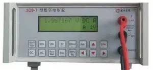 1. Selection of VoltmeterThe principles and methods for selecting a voltmeter are similar to those for selecting an ammeter, mainly considering the measurement object, measurement range, required accuracy, and instrument price. For measurements that do not require high precision, electromagnetic voltmeters are commonly used. For high precision and sensitivity requirements, magnetic electric multi-range voltmeters are often used, among which the voltage range of multimeters is widely used.2. Usage Methods and Precautions1. Ensure that the voltmeter is connected across the two ends of the circuit being measured.2. The range of the voltmeter should be greater than the voltage of the circuit being measured to avoid damaging the voltmeter. 3. When using a magnetic electric voltmeter to measure direct voltage, pay attention to the polarity markings on the voltmeter’s terminals marked “+” and “-”. 4. The voltmeter has internal resistance; the larger the internal resistance, the closer the measurement result is to the actual value. To improve measurement accuracy, use a voltmeter with larger internal resistance whenever possible. 5. When measuring high voltage, use a voltage transformer. The primary coil of the voltage transformer is connected to the circuit being measured, and the secondary coil rated voltage is 100 volts, which connects to a voltmeter with a range of 100 volts. The indicated value of the voltmeter multiplied by the transformation ratio of the voltage transformer gives the actual voltage being measured. During operation, ensure that the secondary coil does not short-circuit; typically, a fuse is set in the secondary coil for protection.Ground Resistance Measurement InstrumentGround resistance refers to the resistance of the grounding body buried underground and the soil leakage resistance.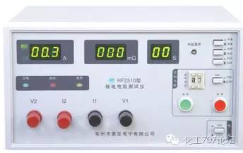
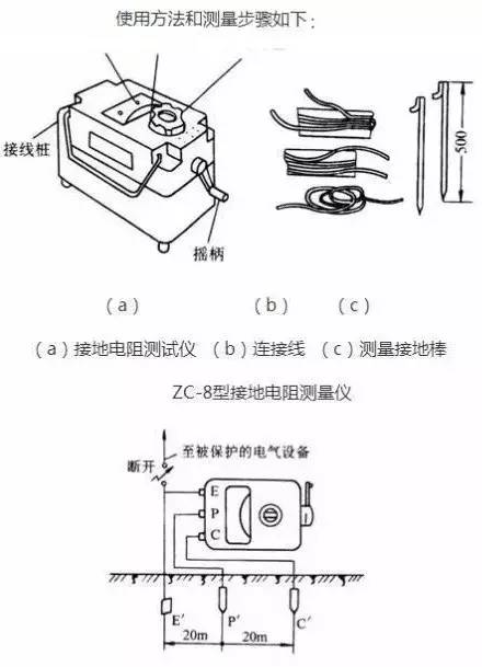 Usage Methods1. Disconnect the connection point between the grounding lead and the grounding body, or disconnect all connection points of the grounding branches on the grounding lead. 2. Insert two grounding rods into the ground to a depth of 400mm, one 40m away from the grounding body and the other 20m away. 3. Place the shake meter on flat ground near the grounding body and then connect the wires. (1) Connect one wire from the meter’s terminal E to the grounding body E′. (2) Connect another wire from the meter’s terminal C to the grounding rod C′ that is 40m away from the grounding body. (3) Connect a wire from the meter’s terminal P to the grounding rod P′ that is 20m away from the grounding body. 4. Adjust the coarse adjustment knob according to the required ground resistance of the measured grounding body (there are three adjustable ranges). 5. Shake the meter evenly at a speed of about 120 revolutions per minute. When the pointer deflects, immediately adjust the fine-tuning dial until the pointer is centered. The reading after fine-tuning multiplied by the coarse adjustment positioning multiple gives the ground resistance of the measured grounding body. For example, if the fine-tuning reading is 0.6 and the coarse adjustment resistance positioning multiple is 10, the measured ground resistance is 6Ω. 6. To ensure the reliability of the measured ground resistance value, change the orientation and re-measure. Take the average of several measured values as the ground resistance of the grounding body.
Source: Thermal Control Circle
If there is any infringement in the content pushed by this account, please inform us, and we will handle it promptly. The internet is an ecological circle for resource sharing, and reprinting is for free dissemination and sharing. This account is not responsible for the authenticity of the reprinted content; the views in the article are for reference only!
For inquiries, contact Tien at 18610813406, WeChat same numberWe take measurement seriously.Haina Measurement F Group QQ 849455800
Haina Measurement Matrix
|
Haina Measurement Official Account |
Haina Measurement Technology Official Account |
Beijing Ruilepu Official Account |
|
Haina Measurement Douyin Account |
Haina Measurement Video Account |
Haina Measurement WeChat Store |