Click ↑ Mechanical Professor, Follow Top to become a top student.
A multimeter, also known as a multimeter, three-use meter, or multifunction meter, is a multifunctional, multi-range measuring instrument. Generally, a multimeter can measure DC current, DC voltage, AC voltage, resistance, and audio level. Some models can also measure AC current, capacitance, inductance, and parameters of semiconductors (like β).
AC Voltage Measurement: As shown in Figure 1, the maximum range is 20V, meaning your input voltage cannot exceed this. The red probe is inserted into the v/Ω hole, and the black probe is inserted into the com hole. The value displayed on the meter is the AC voltage you are measuring.
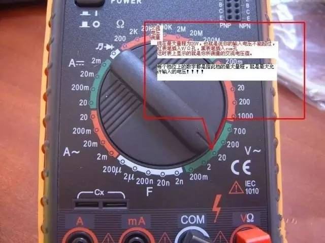 Figure 1
Figure 2 shows five ranges for measuring DC voltage.
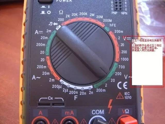 Figure 2
The numbers on the top four ranges represent the maximum current values that can flow through these ranges, as shown in Figure 3.
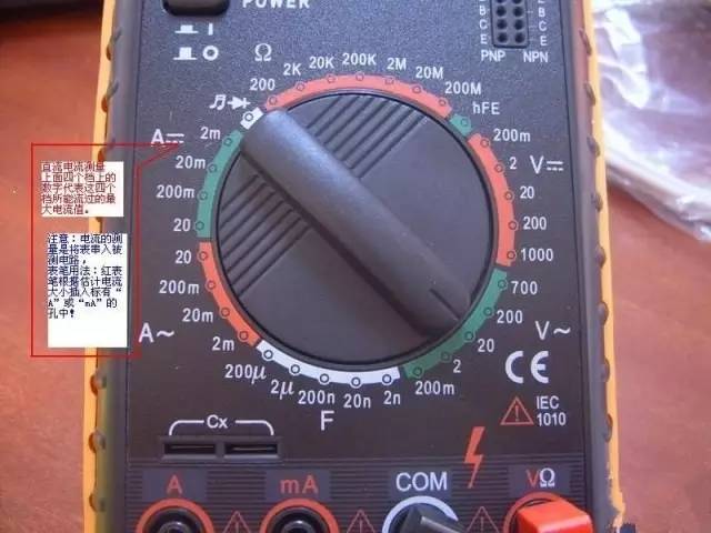 Figure 3
These seven ranges are for resistance measurement. The markings indicate the maximum resistance values that can be measured, as shown in Figure 4.
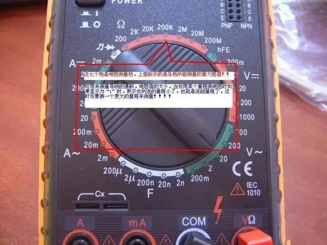 Figure 4
This range is used to test the condition of diodes and check continuity, as shown in Figure 5.
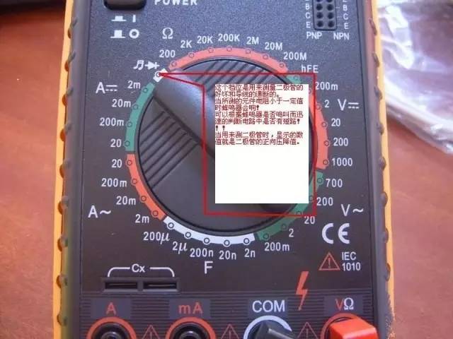 Figure 5
Figure 6 shows the range for measuring capacitance, with markings indicating the maximum capacitance values that can be measured.
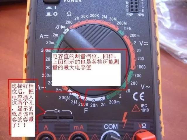 Figure 6
1. Structure of the Multimeter (Model 500)
A multimeter consists of three main parts: the meter head, measuring circuit, and selector switch.
(1) Meter Head
It is a highly sensitive magnetic electric DC ammeter. The main performance indicators of the multimeter depend on the performance of the meter head. The sensitivity of the meter head refers to the amount of DC current flowing through it when the pointer deflects to full scale; the smaller this value, the higher the sensitivity. The internal resistance when measuring voltage is higher, which improves performance. The meter head has four scale lines, which function as follows: The first line (from top to bottom) marked R or Ω indicates resistance value; when the selector switch is in the ohm range, read this line. The second line marked with ∽ and VA indicates AC and DC voltage and DC current values; when the selector switch is in the AC or DC voltage or current position (excluding the AC 10V position), read this line. The third line marked 10V indicates the AC voltage value of 10V; when the selector switch is in the AC or DC voltage range at AC 10V, read this line. The fourth line marked dB indicates audio level.
(2) Measuring Circuit
The measuring circuit is used to convert various measurements into a suitable small DC current for the meter head. It consists of resistors, semiconductor components, and batteries.
It can convert different measurements (such as current, voltage, resistance, etc.) and different ranges into a small DC current of a certain limit through a series of processing (such as rectification, shunting, voltage division, etc.) for measurement by the meter head.
(3) Selector Switch
Its function is to select various measuring circuits to meet different types and ranges of measurement requirements. The selector switch usually has two parts, each marked with different ranges and settings.
2. Symbol Meanings
(1) ∽ indicates AC and DC
(2) V-2.5KV 4000Ω/V indicates for AC voltage and 2.5KV DC voltage range, the sensitivity is 4000Ω/V
(3) A-V-Ω indicates the ability to measure current, voltage, and resistance
(4) 45-65-1000Hz indicates a frequency range below 1000 Hz, with standard power frequency range of 45-65Hz
(5) 2000Ω/V DC indicates the sensitivity of the DC range is 2000Ω/V
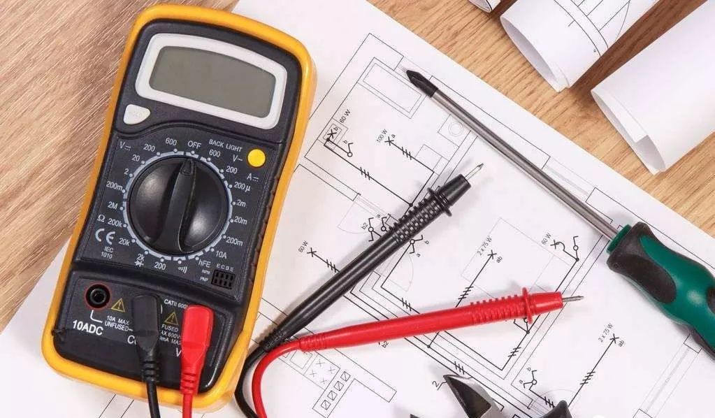
The symbols on clamp meters and shake meters are similar to the above (other symbols cannot be fully written due to formatting issues).
3. Using the Multimeter
(1) Familiarize yourself with the meanings of the symbols on the dial and the main functions of each knob and selector switch.
(2) Perform mechanical zeroing.
(3) Select the range and setting of the selector switch according to the type and size of the measurement, and find the corresponding scale line.
(4) Choose the position of the probe sockets.
(5) Measuring Voltage: When measuring voltage (or current), make sure to select the correct range. Using a small range to measure a high voltage can burn out the meter; if using a large range to measure a small voltage, the pointer deflection may be too small to read. The range selection should ideally make the pointer deflect to about two-thirds of full scale. If the size of the voltage to be measured is unknown, start with the highest range and gradually decrease to the appropriate range.
(a) Measuring AC Voltage: Set one selector switch to AC/DC voltage and the other to the appropriate range for AC voltage. Connect the two probes in parallel with the measured circuit or load.
(b) Measuring DC Voltage: Set one selector switch to AC/DC voltage and the other to the appropriate range for DC voltage. Connect the red probe (+) to the high potential and the black probe (-) to the low potential. This allows current to flow from the red probe to the black probe. If the probes are connected in reverse, the pointer will deflect in the opposite direction, risking bending the pointer.
(6) Measuring Current: When measuring DC current, set one selector switch to DC current and the other to an appropriate range between 50μA and 500mA. The selection of the current range and reading method is the same as for voltage. Before measuring, the circuit must be broken, and the multimeter must be connected in series to the circuit being measured, with current flowing from the red probe to the black probe. If the multimeter is mistakenly connected in parallel with the load, the low internal resistance of the meter head will cause a short circuit and damage the instrument. The reading method is as follows:
Actual Value = Indicated Value × Range / Full Scale Deflection
(7) Measuring Resistance: When using a multimeter to measure resistance, follow these steps:
(a) Select the appropriate multiplier range. The ohm scale is uneven, so the multiplier should be chosen to keep the pointer in the less dense part of the scale, and the closer the pointer is to the middle of the scale, the more accurate the reading. Generally, the pointer should be between 1/3 and 2/3 of the scale.
(b) Perform ohm zeroing. Before measuring resistance, short the two probes and adjust the ohm zero knob to make the pointer point to the zero position just right of the ohm scale line. If the pointer cannot be adjusted to zero, it indicates insufficient battery voltage or an internal problem with the instrument. Also, each time the multiplier range is changed, perform ohm zeroing again to ensure accurate measurements.
(c) Reading: The reading from the meter head multiplied by the multiplier gives the resistance value being measured.
(8) Precautions
(a) Do not change ranges while measuring current or voltage under power.
(b) When selecting a range, start with a larger range and then select a smaller one, aiming to keep the measured value close to the range.
(c) Do not measure resistance while powered. When measuring resistance, the multimeter is powered by its internal battery; measuring under power is like connecting an additional power source, which may damage the meter head.
(d) After use, set the selector switch to the maximum AC voltage range or off.
4. Digital Multimeter
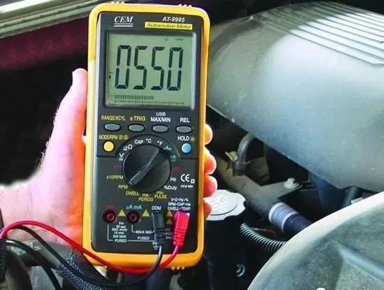
Today, digital measuring instruments have become mainstream and are replacing analog instruments. Compared to analog instruments, digital instruments have higher sensitivity, accuracy, clear display, strong overload capacity, are portable, and easier to use. Below is a simple introduction to the usage and precautions for the VC9802 digital multimeter.
(1) Usage
a. Before use, carefully read the relevant user manual and familiarize yourself with the power switch, range switch, sockets, and special ports.
b. Set the power switch to the ON position.
c. Measuring AC/DC voltage: Depending on the needs, set the range switch to the appropriate range for DCV (DC) or ACV (AC). Insert the red probe into the V/Ω socket, the black probe into the COM socket, and connect the probes in parallel with the circuit being measured. The reading will be displayed.
d. Measuring AC/DC current: Set the range switch to the appropriate range for DCA (DC) or ACA (AC). Insert the red probe into the mA socket (for <200mA) or the 10A socket (for >200mA), the black probe into the COM socket, and connect the multimeter in series with the circuit being measured. When measuring DC, the digital multimeter will automatically display the polarity.
e. Measuring resistance: Set the range switch to the appropriate range for Ω. Insert the red probe into the V/Ω socket, the black probe into the COM socket. If the measured resistance exceeds the maximum value of the selected range, the multimeter will display “1”; at this point, a higher range should be selected. When measuring resistance, the red probe is positive, and the black probe is negative, which is opposite to the pointer-type multimeter. Therefore, when measuring polarized components such as transistors and electrolytic capacitors, be sure to pay attention to the probe polarity.
(2) Usage Precautions
a. If the size of the voltage or current to be measured cannot be estimated in advance, start with the highest range and gradually reduce to an appropriate position. After measurement, set the range switch to the highest voltage range and turn off the power.
b. At full scale, the meter only displays the digit “1” at the highest position, with other positions disappearing; at this point, a higher range should be selected.
c. When measuring voltage, the digital multimeter should be connected in parallel with the circuit being measured. When measuring current, it should be connected in series with the circuit being measured, and when measuring DC, polarity does not need to be considered.
d. If the AC voltage range is mistakenly used to measure DC voltage, or the DC voltage range is mistakenly used to measure AC voltage, the display will show “000” or the digits at the lower position will fluctuate.
e. Do not change the range when measuring high voltage (above 220V) or large current (above 0.5A) to prevent arcing and burning the switch contacts.
f. When the display shows ” ” or “BATT” or “LOW BAT”, it indicates that the battery voltage is below the operating voltage.
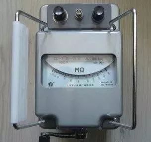
5. Shake Meter
A shake meter, also known as a megohmmeter, is used to measure the insulation resistance and high resistance of the tested equipment. It consists of a hand-cranked generator, meter head, and three connection terminals (L: line terminal, E: ground terminal, G: shield terminal).
1) Selection Principles for Shake Meters
(1) Selection of Rated Voltage Level. Generally, for equipment with a rated voltage below 500V, a shake meter rated at 500V or 1000V should be selected; for equipment rated above 500V, choose a shake meter rated at 1000V-2500V.
(2) Selection of Resistance Range. The scale line of the shake meter has two small black dots, and the area between these dots is the accurate measurement area. Therefore, when selecting a meter, ensure that the insulation resistance value of the tested equipment falls within the accurate measurement area.
2) Using the Shake Meter
(1) Calibration. Before measurement, perform an open circuit and short circuit test on the shake meter to check if it is functioning properly. Leave the two connection wires open, crank the handle, and the pointer should point to “∞”. Then short the two connection wires, and the pointer should point to “0”. If both conditions are met, it is functioning properly; otherwise, it cannot be used.
(2) Disconnect the tested equipment and circuit, and discharge large capacitive devices.
(3) Select a shake meter with a voltage rating that matches.
(4) When measuring insulation resistance, generally only the “L” and “E” terminals are used. However, when measuring the insulation resistance of cables to ground or when leakage current from the tested equipment is severe, use the “G” terminal and connect it to the shielding layer or casing. After the circuit is connected, crank the handle clockwise. The speed of cranking should start slowly and then increase. When the speed reaches about 120 revolutions per minute (for model ZC-25), maintain a constant speed and read the value after one minute. Read while cranking; do not stop to read.
(5) Disconnect and discharge. After reading, slowly crank while disconnecting the wires, then discharge the tested equipment. The discharge method is to remove the ground wire used during measurement from the shake meter and short it to the tested equipment (not discharging the shake meter).
3) Precautions
(1) Do not measure insulation resistance during thunderstorms or near high voltage equipment; measurements should only be done when the equipment is not powered and there is no induced voltage.
(2) During the shaking test, no one should work on the tested equipment.
(3) The shake meter wires should not be twisted together; keep them separated.
(4) Do not touch the shake meter or the tested equipment until the shake meter has stopped turning or the equipment has been discharged. When disconnecting wires, do not touch the metal parts of the leads.
(5) At the end of the measurement, discharge large capacitive devices.
(6) Regularly calibrate its accuracy.
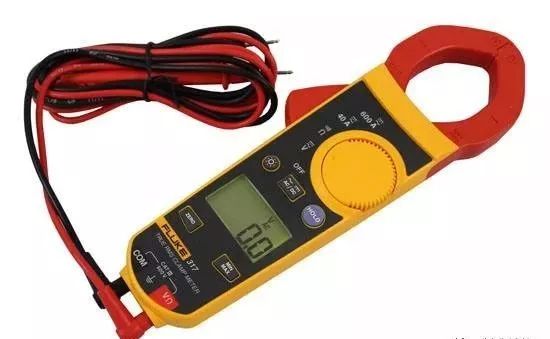
6. Clamp Meter
A clamp meter is an instrument used to measure the current of electrical circuits in operation without interrupting the power supply.
1) Structure and Principle
A clamp meter essentially consists of a current transformer, clamp-type wrench, and a rectifying magnetic electric system with reactive force.
2) Using the Clamp Meter
(1) Perform mechanical zeroing before measurement.
(2) Choose the appropriate range, starting with a large range and then selecting a smaller one or estimating based on the nameplate value.
(3) When using the smallest range, if the reading is not clear, the wire being measured can be wrapped a few times; the number of turns should be based on the turns at the center of the clamp. The reading will be: Reading = Indicated Value × Range / Full Scale Deflection × Number of Turns.
(4) During measurement, ensure the wire being measured is centered in the clamp and that the clamp is closed tightly to minimize error.
(5) After measurement, set the selector switch to the maximum range.
3) Precautions
(1) The voltage of the measured circuit should be lower than the rated voltage of the clamp meter.
(2) When measuring the current of high voltage lines, wear insulated gloves, insulated shoes, and stand on an insulating mat.
(3) The clamp must be closed tightly; do not change the range while powered.
What do you think about this? Everyone is welcome to leave comments for discussion.
I am a professor.
Long press the QR code to add me.
WeChat ID: jixiejiaoshou