 Search on WeChat
 Technical Training01Introduction to Digital Multimeter
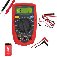
Digital measuring instruments have become mainstream due to their high sensitivity, accuracy, clear display, strong overload capacity, portability, and ease of use.
▲ Figure 1
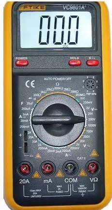
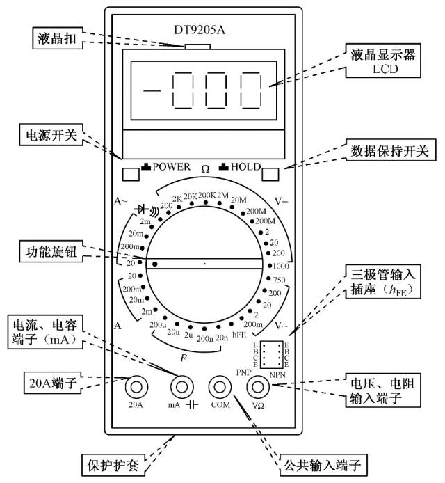
Below, we will use this type of digital multimeter as an example to briefly introduce its usage methods and precautions.02Appearance of Digital Multimeter
03Digital Multimeter Usage Illustration
04Measuring Voltage
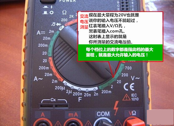
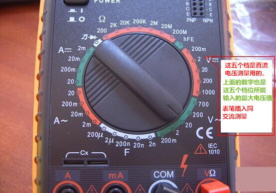
1. Insert the black probe into the COM port and the red probe into the VΩ port.
2. Rotate the function switch to V~ (AC), V- (DC), and select the appropriate range.
3. Touch the red probe to the positive side of the circuit being tested, and the black probe to the ground or negative side, connecting them in parallel with the circuit.
4. Read the number on the LCD display.
05Measuring Resistance
1. Turn off the power to the circuit.
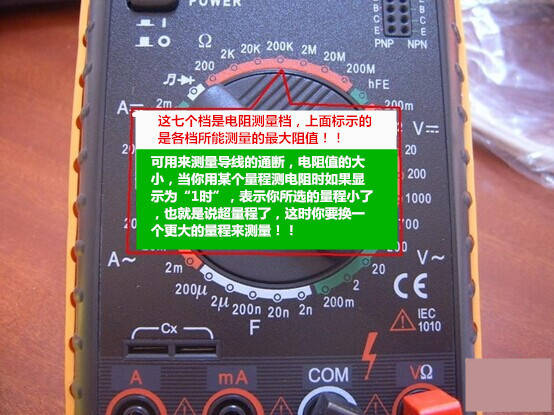
2. Select the resistance range (Ω).
3. Insert the black test probe into the COM input socket. Insert the red test probe into the Ω input socket.
4. Connect the probe tips across the component you want to measure or across the part of the circuit.
5. Check the reading, confirming the measurement unit – ohms (Ω), kilohms (kΩ), or megohms (MΩ).
06The Function of the Diode Beep Mode① Judging the Condition of the Diode
Set the dial to the diode mode ( ), insert the red probe into the rightmost hole, and the black probe into the second hole from the right. Connect the probe tips to both ends of the diode as shown in the diagram, then reverse the probes and measure again.
The measurement results are as follows: If the results from both measurements are: one shows “1” and the other shows a number close to zero, then this diode is a normal diode. If both measurements show the same result, then this diode is damaged. The number displayed on the LCD is the forward voltage drop of the diode: approximately 0.6V for silicon diodes; approximately 0.2V for germanium diodes. Based on the characteristics of the diode, you can determine that the red probe is connected to the positive side of the diode, and the black probe is connected to the negative side.
One of the most important characteristics of a diode is:
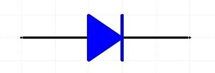
▲ Unidirectional Conductivity
② Short Circuit Check (Judging Circuit Continuity):
Set the dial to the short circuit mode (), with the same probe positions as above. Connect the other ends of the probes to the two points being tested. If these two points are indeed shorted, the multimeter’s buzzer will sound.
07Measuring Current
1. Disconnect the circuit;
2. Insert the black probe into the COM port, and the red probe into the mA or 20A port;
3. Rotate the function switch to A~ (AC), A- (DC), and select the appropriate range;
4. Disconnect the circuit being tested, and connect the digital multimeter in series with the circuit being tested. The current from one end of the circuit flows into the red probe, through the black probe of the multimeter, and back into the circuit;
5. Reconnect the circuit;
6. Read the number on the LCD display.
08Measuring Capacitance
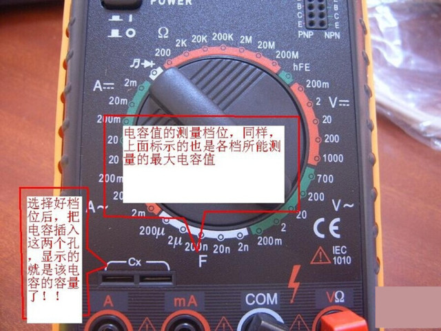
1. Short the capacitor terminals to discharge it, ensuring the safety of the digital multimeter.
2. Rotate the function switch to the capacitance (C) measurement range and select the appropriate range.
3. Insert the capacitor into the C-X socket of the multimeter.
4. Read the number on the LCD display.
Fun Fact: The unit of capacitance:
1F=1000mF=1000uF=1000nF=1000pF
09Precautions for Using Digital Multimeter
1. If you cannot estimate the size of the voltage or current to be measured in advance, you should first set it to the highest range and measure once, then gradually reduce the range to an appropriate position based on the situation. After measuring, the range switch should be set to the highest voltage range and the power turned off.
2. At full scale, the instrument will only display the digit “1” at the highest position, and all other positions will disappear. At this time, a higher range should be selected.
3. When measuring voltage, the digital multimeter should be connected in parallel with the circuit being tested. When measuring current, it should be connected in series with the circuit being tested. When measuring DC, polarity does not need to be considered.
4. When incorrectly using the AC voltage range to measure DC voltage, or using the DC voltage range to measure AC voltage, the display will show “000”, or the digits at the lower positions will fluctuate.
5. Do not change the range when measuring high voltage (above 220V) or large current (above 0.5A) to prevent arcing and damaging the switch contacts.
Disclaimer: This article is reprinted from the internet, and the copyright belongs to the original author. If there are any copyright issues, please contact us in a timely manner for removal. Thank you!
HISTORY/Previous Recommendations
Complete Question Bank for Beginner Electrician Exam 2021 (Including Answers)
Is troubleshooting inverter faults difficult? Just one click!
Can you brush through all electrical exam questions with one click? Don’t you have this gadget yet?
Which of the five major electrical drawing software (CAD, Eplan, CADe_simu…) do you choose?
Latest Electrical CAD Drawing Software, with super detailed installation tutorial!
Latest Electrical Drawing Software EPLAN, with super detailed installation tutorial!
Common Issues When Beginners Use S7-200 SMART Programming Software (with download link)
Comprehensive Electrical Calculation EXCEL Sheets, automatically generated! No need to seek help for electrical calculations!
Bluetooth headsets, electrician/PLC introductory books are freely given away? Come and claim your electrical gift!
Basic Skills in PLC Programming: Ladder Diagrams and Control Circuits (with 1164 practical cases for Mitsubishi PLC)
Still can’t understand electrical diagrams? Basics of electrician diagram reading, simulation software available, quickly get started with theory and practice!
12 free electrician video courses, 10GB software/e-book materials, and 30 days of free live electrician classes are being given away!
Don’t forget to like + view!