Scientifically selecting bandwidth allows your oscilloscope to “see clearly” and “measure accurately”.
Have you encountered these issues?
The signal source outputs perfectly, but the waveform displayed on the oscilloscope is distorted, with unclear edges and inaccurate amplitude? The problem often lies in the choice of bandwidth. In the field of electronic measurement, the oscilloscope is the engineer’s “eye”, and bandwidth is the “vision range” of this eye. Choosing the appropriate bandwidth not only affects the accuracy of signal measurement but also directly impacts R&D efficiency and product quality. We will analyze how to scientifically choose oscilloscope bandwidth by combining theory with practical case studies.
1. The Essence of Bandwidth: The “Threshold” of Frequency Response
The bandwidth of an oscilloscope is defined as the frequency at which a sine wave input signal is attenuated to 70.7% of its true amplitude, known as the -3 dB point. This metric reflects the oscilloscope’s ability to capture high-frequency signals. For example, a 1GHz bandwidth oscilloscope will attenuate a 1V signal to about 700mV at the 1GHz frequency point, with even greater attenuation for higher frequency signals.
From the perspective of frequency response characteristics, oscilloscopes below 1GHz typically use Gaussian response (Figure 1), which has a gentle roll-off characteristic suitable for fast edge measurements; above 1GHz, maximum flat response (Figure 2) is commonly used, providing more stable in-band signals but with a steeper high-frequency roll-off. Both characteristics have their pros and cons: Gaussian response oscilloscopes have faster rise times at the same bandwidth (approximately 0.35/fBW @10%-90% RT), while maximum flat response oscilloscopes offer higher measurement accuracy for in-band signals.
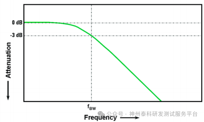
Figure 1. Gaussian Response
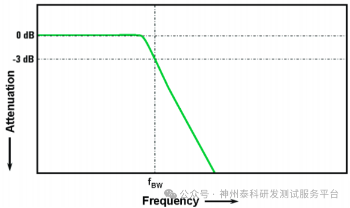
Figure 2. Maximum Flat Response
2. Digital Applications: From Rules of Thumb to Precise Calculations
1. Rule of Thumb: 5 times the clock frequency.
For digital signals, the general recommendation is that the bandwidth should be at least 5 times the highest clock frequency. For example, a 100MHz clock signal requires a 500MHz bandwidth oscilloscope to ensure that the fifth harmonic (500MHz) is effectively captured. If a 100MHz bandwidth oscilloscope is used, the measured waveform will be severely distorted, resembling a sine wave. However, if precise measurements are needed on fast signal edges, this simple formula cannot reflect the high-frequency components that actually exist in the rapid rise and fall times.
2. Precise Method: Calculating the “Knee Frequency” (f_knee) based on edge speed.
When precise measurements of high-speed edges are required, the “Knee Frequency” (f_knee) calculation method should be used. The core is to first calculate the signal’s f_knee, then multiply by the corresponding bandwidth factor based on measurement accuracy requirements, and finally determine the oscilloscope bandwidth. This can be completed in three steps:
(1) Step One: Calculate the signal’s f_knee.
The formula for calculating f_knee varies depending on the definition of rise time.

Some devices specify the maximum signal conversion rate (SR) instead of rise time, and the following formula can be used to approximate the 20% to 80% rise time.
RT (20%-80%)≈ 0.6 (VH-VL) / SR
(2) Step Two: Select the bandwidth factor based on accuracy requirements.
The frequency response characteristics of oscilloscopes (Gaussian response / maximum flat response) differ, and the required bandwidth multiplier (i.e., “accuracy factor”) varies under the same accuracy. Below is a commonly used accuracy factor correspondence table in the industry:
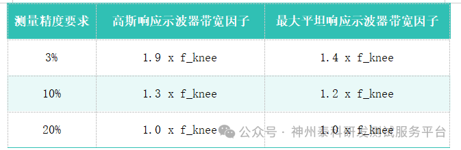
Note: The factor values are sourced from the technical white papers of oscilloscope manufacturers (such as Keysight, Tektronix, etc.), derived from measured frequency response curves.
(3) Step Three: Calculate the required bandwidth based on the selected bandwidth factor.
Taking the example of a “500ps rise time (10%-90%), requiring 3% measurement accuracy”:
A.First calculate f_knee: f_knee = 0.5 / 500ps = 1GHz
B.Select factor: The factor for Gaussian response oscilloscopes is 1.9 times
C.Determine bandwidth: Required oscilloscope bandwidth= 1GHz × 1.9 = 1.9GHz
D.Actual selection should round up, choosing a 2GHz bandwidth oscilloscope (to allow for some margin).
3. Analog Applications: The 3x Rule and Response Flatness
For analog signals (such as sine wave signals), the bandwidth generally follows the 3x rule: the bandwidth should be at least 3 times the highest signal frequency. For example, a 100MHz sine wave requires a 300MHz bandwidth oscilloscope. It is important to note that this rule assumes the oscilloscope has a flat response in the low-frequency range.
4.Typical Case Studies
Below we will look at a practical case to see the waveforms captured with different oscilloscope bandwidth settings. We used a signal source to output a 20MHz square wave, 50% duty cycle, with a rise time set to 4ns and an amplitude of 500mVpp.
Setting the oscilloscope bandwidth to 20MHz, as shown in Figure 3. The waveform is already distorted, and both the rise time and amplitude differ significantly from the set values.
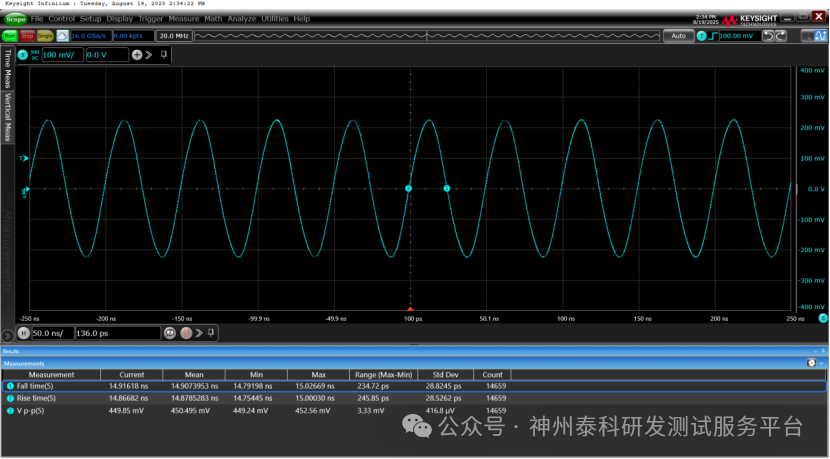
Figure 3. 20MHz
Then setting the oscilloscope bandwidth to 3 times the signal frequency, i.e., 60MHz, as shown in Figure 4. The waveform is still somewhat distorted, the amplitude is close to the set value, but the rise time (6.8ns) and the set value (4ns) still have some discrepancy.
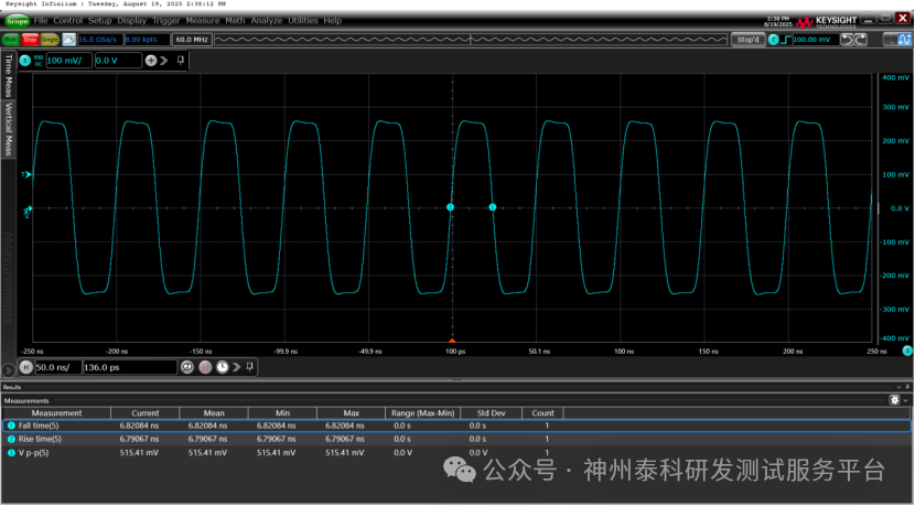
Figure 4. 60MHz
When setting the oscilloscope bandwidth to 5 times the signal frequency, i.e., 100MHz, as shown in Figure 5. The rise time (5.09ns) and the set value (4ns) have further narrowed the gap.
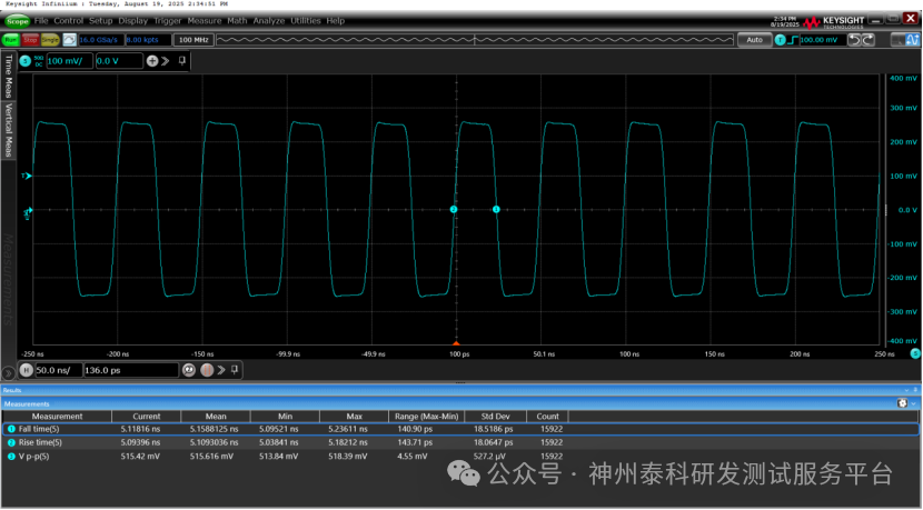
Figure 5. 100MHz
When the oscilloscope bandwidth is set according to the frequency calculated from the knee frequency, i.e., 238MHz, as shown in Figure 6. At this point, the rise time reaches 4.13ns, which is very close to the original signal waveform.
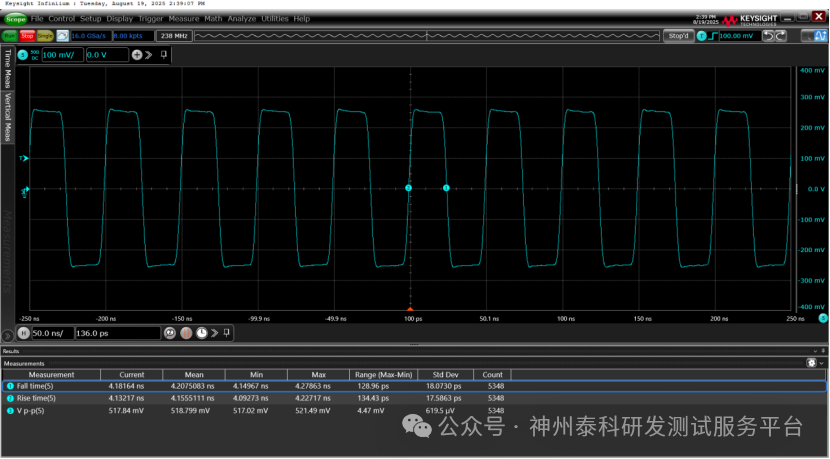
Figure 6. 238MHz
5.Conclusion
Choosing oscilloscope bandwidth must balance theoretical calculations with practical scenarios. In digital applications, bandwidth can be quickly selected based on the rule of thumb—5 times the clock frequency. If more attention is paid to rise or fall times, using the f_knee method (including accuracy factor selection) can precisely match edge speeds, avoiding over or under-selection; for analog applications, it is essential to ensure response flatness, following the 3x rule. By allowing for margin, and focusing on manufacturer technical support (such as Keysight’s real-time de-embedding function), an optimal solution can be found between cost and performance.
Bandwidth is the foundation of an oscilloscope’s ability to see the high-speed world clearly. However, just as human eyes need to coordinate with other senses, the collaborative optimization of metrics such as sampling rate, storage depth, and triggering capability is necessary to truly unleash the oscilloscope’s full measurement potential.
Accurate measurements rely on professional tools and methods.
Shenzhou Taike’s high-speed signal laboratory has fully established testing capabilities for the physical layer consistency of mainstream high-speed interfaces such as HDMI, DP, PCIe, USB, DDR, GMSL, and MIPI, providing you with one-stop support from precise selection to professional verification.
Welcome to make an appointment!