In many industrial and automotive applications, protecting interface transceivers from various electrical overstress events is a major concern. Transient Voltage Suppressor (TVS) diodes are commonly used for this purpose as they can clamp voltage spikes by creating a low-impedance current path.
The electrical characteristics of TVS diodes are determined by several process factors. These parameters relate to TVS voltage, current, and power ratings, with a wide range of values to accommodate various applications. However, selecting the right component is not straightforward when reviewing the component datasheet. In this article, I will discuss the voltage parameters and demonstrate which TVS diodes are suitable for RS-232, RS-485, and Controller Area Network (CAN) applications. Of course, peak pulse power dissipation and peak pulse current are also critical parameters that determine the discharge capability and Electrostatic Discharge (ESD) levels in the system. However, I will focus on voltage here.
TVS Voltage Parameters VWM, VBR, and VC
When an unwanted high-voltage transient occurs, the TVS diode should clamp the voltage; it should also be “transparent” when the transceiver operates under normal conditions. Therefore, the first parameter to check on the datasheet is the rated standoff voltage VWM. VWM, also known as the rated working voltage, indicates that below this voltage, the TVS is open-circuit and has low standby leakage current.
When selecting a component, you want VWM to be greater than the recommended operating range of the transceiver. As the input voltage increases, the TVS begins to break down and conducts more current at VBR. More importantly, the maximum voltage parameter VC, which is the clamping voltage under high current pulse conditions, must be considered. VC represents the maximum clamping voltage at a specific pulse current. When comparing VC with the transceiver parameters, you need to ensure it does not exceed the absolute maximum rating of the integrated circuit (IC). The “absolute maximum” is the maximum voltage limit allowed for the transceiver at any time. Any voltage above this limit will place the transceiver in an unsafe operating region and may lead to complete failure.
Example: TVS Selection for RS-232, RS-485, and CAN Transceivers
I will introduce several example devices for RS-232, RS-485, and CAN transceivers and their corresponding TVS diode selections. I have gathered relevant parameters from their respective datasheets, and I hope to provide insight into how different components work together by presenting these parameter values.
TI’s MAX3232 is a common RS-232 transceiver with two transmitters and two receivers. I have highlighted two important parameters in Figures 1 and 2: a working voltage of ±5.4V and an absolute maximum driver output voltage of ±13.2V. According to the RS-232 standard, the signal swing should be above ±5V. Here, you can allow some margin.
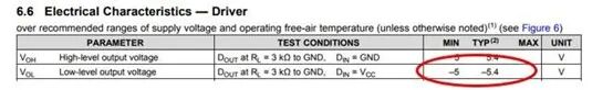
Figure 1: MAX3232 Driver Working Voltage
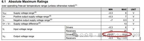
Figure 2: MAX3232 Driver Absolute Maximum Ratings
The suitable TVS diode for the MAX3232 is Bourns’ SMBJ8.0CA. As shown in Figure 3, the peak reverse working voltage is 8V, and the maximum clamping voltage is 13.6V.
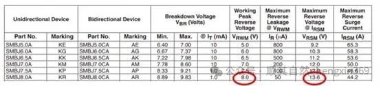
Figure 3: SMBJ8.0CA Peak Reverse Working Voltage and Maximum Clamping Voltage
Next, let’s look at the 8-pin RS-485 transceiver, TI’s THVD1500. According to the RS-485 standard, RS-485 transceivers can operate over a wide common-mode range (-7V to 12V) (Figure 3). As shown in Figure 4, the absolute maximum voltage for the THVD1500 bus pins is ±18V.
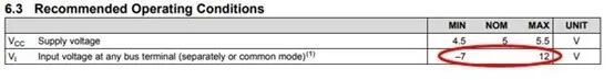
Figure 4: THVD1500 Driver Working Voltage
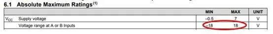
Figure 5: THVD1500 Driver Absolute Maximum Ratings
SM712 is a common TVS diode for RS-485 applications. This TVS has an asymmetric reverse standoff voltage that matches the common-mode operating range of RS-485 applications. Additionally, its clamping voltage is close to the limits of the TI THVD1500, as shown in Figure 6.
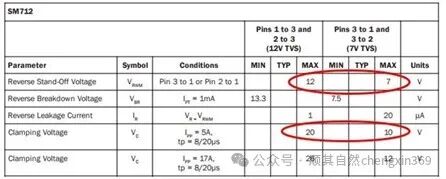
Figure 6: SM712 Reverse Standoff Voltage and Clamping Voltage
Last but not least, the TI SN65HVD1040A 8-pin CAN transceiver has a relatively high absolute maximum voltage (Figure 7), which simplifies the selection of TVS. Similar to RS-485, the CAN bus can also tolerate some common-mode voltage variations (Figure 8).
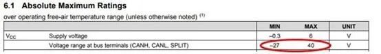
Figure 7: SN65HVD1040A Driver Absolute Maximum Ratings
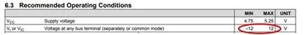
Figure 8: SN65HVD1040A Driver Working Voltage
Considering all factors, Bourns’ CDSOT23-T24CAN is a suitable device for the SN65HVD1040A. This device offers a reverse working voltage of 24V and a clamping voltage of 36V to 40V. To save space, I have not copied the datasheet here. However, I believe that based on the first two examples, finding the relevant parameters will not be too difficult.
Voltage parameters are just part of the electrical characteristics of TVS devices, but they are a primary consideration when selecting a TVS. To better understand the full characteristics of TVS devices, you can also look at other parameters, such as peak power and peak current.
Source: https://e2echina.ti.com