The RS-485 bus is widely used in communication, industrial automation, and other fields. In practical applications, one often encounters the question of whether to add pull-up and pull-down resistors and what resistance values are appropriate. Below, we will conduct a detailed analysis of these issues.
1. Why are Pull-Up and Pull-Down Resistors Needed?
According to the RS-485 standard, when the differential voltage on the 485 bus exceeds +200mV, the 485 transceiver outputs a high level; when the differential voltage is less than -200mV, it outputs a low level. When the voltage on the 485 bus is between -200mV and +200mV, the 485 transceiver may output either a high or low level, but it generally remains in one state. If the output is low, this represents a start bit for UART communication, which can lead to communication issues.
When the 485 bus is open (the 485 transceiver is disconnected from the bus) or in an idle state (all 485 transceivers are in receive mode, and no transceiver is driving the bus), the differential voltage on the 485 bus is essentially 0, placing the bus in an uncertain state. Additionally, current 485 chips are designed with high input impedance to increase the number of nodes on the bus, such as an input impedance of 1/4 or 1/8 of the unit impedance (with a unit impedance of 12kΩ, 1/4 unit impedance is 48kΩ), making it susceptible to electromagnetic interference when the pins are floating.
To prevent the 485 bus from entering the aforementioned states, pull-up and pull-down resistors are typically added to the 485 bus (usually a pull-up resistor on A and a pull-down resistor on B). If using an isolated RS-485 transceiver module (e.g., RSM485PCHT), since the module has internal pull-up and pull-down resistors (for RSM485PCHT, the internal resistors are 24kΩ), external pull-up and pull-down resistors are generally not needed.
2. When are Pull-Up and Pull-Down Resistors Required?
When encountering signal reflection issues, matching resistors are typically added to avoid signal reflections. For example, in a 1-to-1 communication scenario, as shown in Figure 1, since the 485 bus usually uses twisted pair cable with a characteristic impedance of 120Ω, 120Ω termination resistors are added at both ends of the 485 bus to mitigate signal reflection issues.
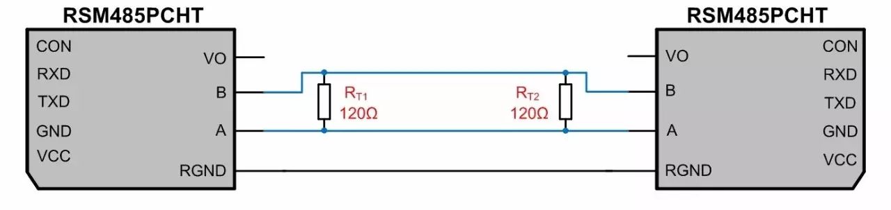 Figure 1 Communication Circuit of Two RSM485PCHT Modules
Based on the specific parameters of RSM485PCHT (as shown in Table 1), the equivalent circuit can be derived as shown in Figure 2, where RPU and RPD are the internal pull-up and pull-down resistors added to the 485 bus, and RIN is the input impedance of the module.
Table 1 RSM485PCHT Parameters
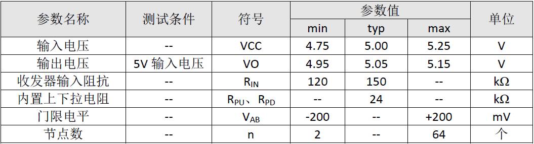
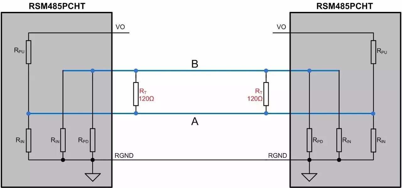 Figure 2 RSM485PCHT Communication Equivalent Diagram
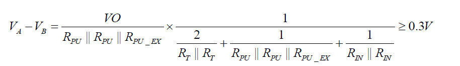
When both modules are in receive mode, we can apply Kirchhoff’s current law to nodes A and B to derive the following equations:

From the above equations, the differential voltage between A and B can be calculated as:
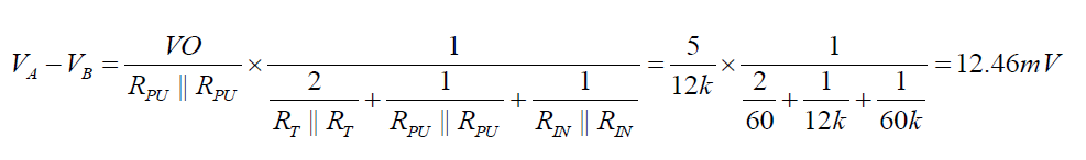
At this point, the module is in an uncertain state, and the receiver may output either a high or low level. Therefore, it is necessary to add external pull-up and pull-down resistors to ensure that the module does not remain in an uncertain state when idle.
3. How to Select Pull-Up and Pull-Down Resistors?
Assuming the output power supply voltage V¬O is the same, since RGND is connected together, the internal pull-up resistors of the module can be considered to be in parallel. For ease of explanation, the circuit in Figure 2 is reorganized as shown in Figure 3, where one set of pull-up and pull-down resistors can be added externally, or each module can have its own set of resistors. For simplicity, we will add one set of pull-up and pull-down resistors to the 485 bus.
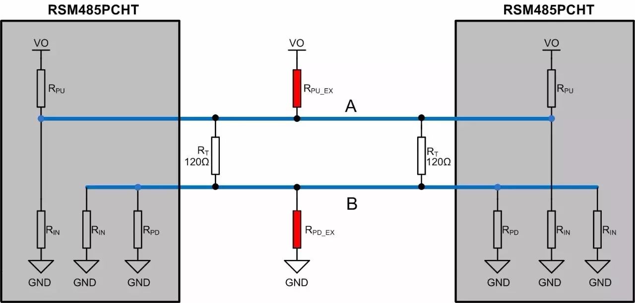 Figure 3 RSM485PCHT Communication Equivalent Circuit Diagram
Where:
RPU is the internal pull-up resistor of the module, RPD is the internal pull-down resistor, which in this case is 24kΩ;
RIN is the receiver input impedance of the module, taken as a minimum value of 120kΩ;
RT is the termination resistor, taken as 120Ω in this case;
RPU_EX is the external pull-up resistor added to the module, and RPD_EX is the external pull-down resistor added to the module;
Since the threshold level of RSM485PCHT is -200mV to +200mV, a voltage margin of 100mV or 200mV is generally reserved. In this case, a margin of 100mV is reserved. Based on the previously derived differential voltage formula, the following calculation formula can be obtained:
Since RSM485PCHT operates within a supply voltage range of 4.75V to 5.25V, taking VO=4.75V (the minimum input voltage VCC=4.75V), we can derive:
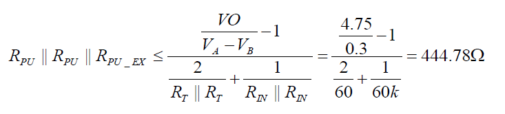
From RPU=24kΩ, we find RPU_EX=RPD_EX=461.9Ω. Since the calculated resistance value is a maximum, we can choose to add a single set of 410Ω or 390Ω pull-up and pull-down resistors to the 485 bus, or two sets of 910Ω pull-up and pull-down resistors.
4. How to Validate the Selected Values for Pull-Up and Pull-Down Resistors?
The above calculations only consider the idle state of the 485 bus and do not account for the driving capability of the 485 transceiver and the power consumption of the components used. The smaller the external pull-up and pull-down resistors, the higher the differential voltage can be maintained during the idle state of the 485 bus. However, this also increases the power consumption of the termination resistors and pull-up/pull-down resistors, which raises the requirements for the driving capability of the 485 transceiver. If the driving capability is exceeded, communication failures may occur.
According to the RS-485 standard, when the input impedance of the receiver is equal to the unit impedance (minimum 12k), a maximum of 32 nodes can be connected to the bus, and the maximum differential load for 485 is 54Ω. At this point, the minimum differential output voltage is 1.5V.
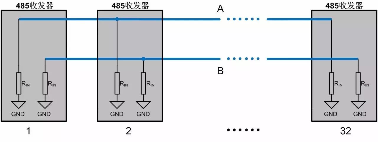 Figure 4 Equivalent Diagram of 32 Nodes Connected to the 485 Bus
As shown in Figure 4, when 32 nodes are connected to the 485 bus, the common-mode load on bus A or B is:
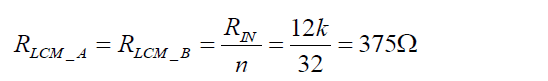
Thus, for the RS-485 standard, the maximum common-mode load on bus A or B is 375Ω.
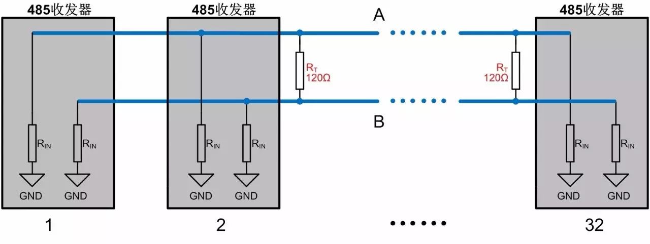 Figure 5 Equivalent Diagram of Adding Termination Resistors to the 485 Bus
When termination resistors are added, it can be observed that the common-mode load on the 485 bus does not change, but the differential load decreases sharply, with the differential load being:
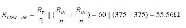
Therefore, when the number of nodes on the 485 bus reaches the maximum and termination resistors are added, the differential load on the 485 bus remains greater than 54Ω. According to the RS-485 standard, the minimum differential output voltage is 1.5V.
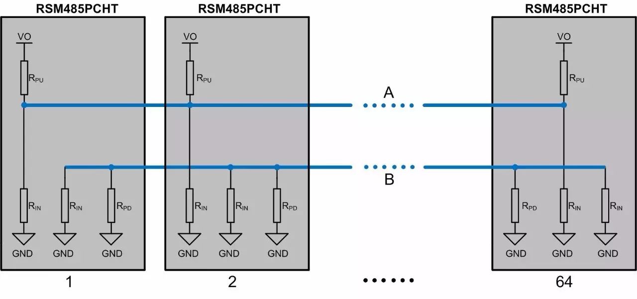 Figure 6 Equivalent Diagram of RSM485PCHT with 64 Nodes
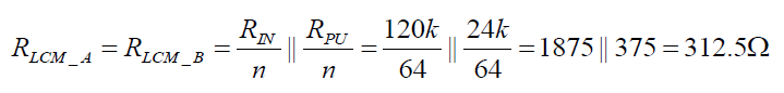
Using RSM485PCHT as an example to illustrate the situation of adding pull-up and pull-down resistors, as shown in Figure 6, the common-mode load on bus A or B is:
Actual testing of the above situation shows that the minimum differential voltage output is 3.02V, which is significantly higher than the minimum differential output voltage of 1.5V specified by the RS-485 standard.
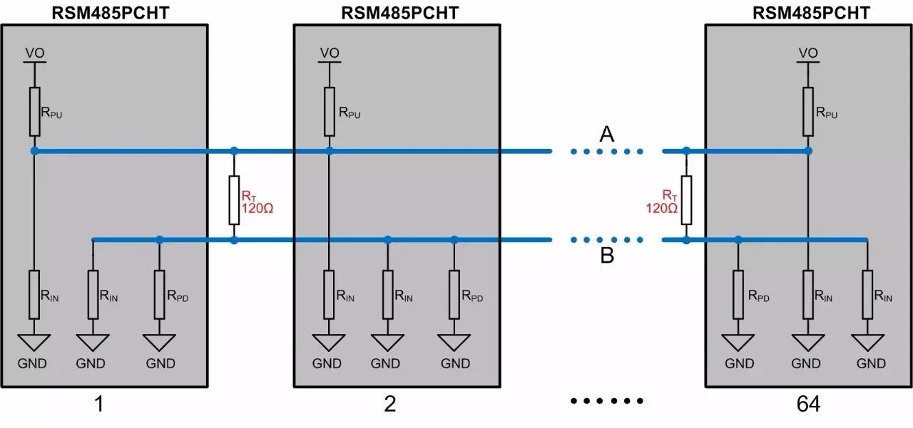 Figure 7 RSM485PCHT with 64 Nodes and Added Termination Resistors
When termination resistors are added to the 485 bus, it can be seen that the common-mode load on bus A or B does not change, while the differential impedance changes significantly, resulting in a differential load of:
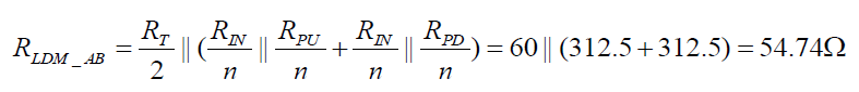
The calculated differential load is slightly greater than the maximum load of 54Ω specified by the RS-485 standard. Testing of RSM485PCHT shows that its output differential voltage is 1.58V, which is slightly above the minimum voltage specified by the standard.
When the differential load is 54Ω (with two 120Ω termination resistors connected to the 485 bus and the parallel value of the pull-up and pull-down resistors with the transceiver’s internal resistance being 270Ω), the differential output voltage of RSM485PCHT is 1.52V (measured value), which is essentially in line with the RS-485 standard. When the differential load is 41.54Ω (with two 120Ω termination resistors connected to the 485 bus and the parallel value of the pull-up and pull-down resistors with the transceiver’s input impedance being 135Ω), the differential output voltage of RSM485PCHT is around 1.17V (measured value), which allows for communication. However, the maximum differential load specified in the transceiver’s manual is usually 54Ω, meaning that after adding two 120Ω termination resistors to the 485 bus, the parallel value of the pull-up and pull-down resistors with the transceiver’s input impedance should be greater than 270Ω. To ensure stable and reliable communication, the parallel value of the pull-up and pull-down resistors with the transceiver’s input impedance should generally be greater than 375Ω.
5. Conclusion
-
Communication lines should use shielded twisted pairs, with the shield connected to ground at a single point;
-
When we do not encounter signal reflection issues, it is best not to use termination resistors;
-
If termination resistors are used, we can adjust the voltage value of the 485 bus in idle state through pull-up and pull-down resistors to ensure it does not fall within the threshold level (-200mV to +200mV or -200mV to -40mV);
-
When we add pull-up and pull-down resistors, the parallel value of the pull-up and pull-down resistors with the transceiver’s input impedance should be greater than 375Ω.
Official WeChat Account Introduction
The official WeChat account of Zhiyuan Electronics, a platform gathering 500 engineers for R&D and testing sharing, providing you with leading product technologies and solutions in the electronics industry..