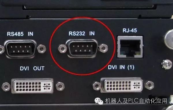
RS-232 is a serial data communication interface standard established by the Electronic Industries Alliance (EIA) in the United States, originally designated as EIA-RS-232 (commonly referred to as 232, RS232). It is widely used for connecting computer serial interface peripherals.
The RS-232C standard, where EIA (Electronic Industry Association) represents the Electronic Industries Alliance of the United States, RS (Recommended Standard) denotes the recommended standard, 232 is the identifier, and C indicates the third revision of RS232 (in 1969). Prior to this, there were also RS232B and RS232A.
The latest version is issued by the Telecommunications Industry Association (TIA), which was split off from the EIA, known as TIA-232-F, and it is also recognized as the American National Standard ANSI/TIA-232-F-1997 (R2002), which was reaffirmed in 2002. The numbering at the time of issuance in 1997 was TIA/EIA-232-F and ANSI/TIA/EIA-232-F-1997. The previous version was TIA/EIA-232-E.[1]
It specifies the connection cable and mechanical, electrical characteristics, signal functions, and transmission processes. Other commonly used electrical standards include EIA-RS-422-A, EIA-RS-423A, and EIA-RS-485.
Currently, the COM1 and COM2 ports on IBM PCs are RS-232C interfaces. RS-232 defines the electrical characteristics, logic levels, and various signal line functions.
Due to the significant impact of RS-232-C, even though the IBM PC/AT began using 9-pin connectors, the 25-pin connectors specified in RS-232 are almost no longer used, but most people still commonly use RS-232C to represent this interface.
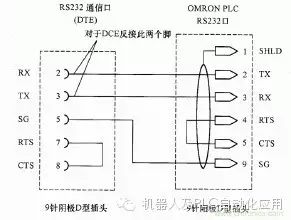
RS-232 was originally designed to connect modems for transmission, and thus its pin meanings are often related to modem transmission. RS-232 devices can be classified into two categories: Data Terminal Equipment (DTE, for example, PC) and Data Communication Equipment (DCE). This classification defines different lines used to send and receive signals. Generally, computers and terminal devices have DTE connectors, while modems and printers have DCE connectors. However, this is not always strictly correct, and testing connections with wiring splitters or using trial-and-error methods to determine whether cables work often requires reference to relevant documentation.
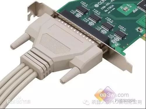
RS-232 specifies 20 different signal connections, consisting of a DB-25 connector made up of 25 D-sub (mini D-type) pins. Many devices only use a small portion of these pins, and to save costs and space, many machines adopt smaller connectors, particularly the 9-pin D-sub or DB-9 type connectors, which are widely used in most PCs and many other devices since the IBM AT machine. The DB-25 and DB-9 connectors are predominantly female on most devices, but not all are like this. Recently, the 8-pin RJ-45 connector has become increasingly common, although its pin assignments vary widely. The EIA/TIA 561 standard specifies a method for pin assignment, but the widely used Yost Serial Device Wiring Standard, invented by Dave Yost for Unix computers, and many other devices do not adopt either of the aforementioned wiring standards.
Mechanical Characteristics
Connectors: Since RS-232C does not define the physical characteristics of connectors, various types of connectors such as DB-25, DB-15, and DB-9 have emerged, each with different pin definitions. The following introduces two types of connectors.
(1) DB-25: PC and XT machines use the DB-25 connector. The DB-25 connector defines 25 signal lines divided into 4 groups:
① 9 voltage signals for asynchronous communication (including signal ground SG) 2, 3, 4, 5, 6, 7, 8, 20, 22
② 9 signals for 20mA current loop (12, 13, 14, 15, 16, 17, 19, 23, 24)
③ 6 vacant signals (9, 10, 11, 18, 21, 25)
④ 1 protective ground (PE) as the device grounding terminal (pin 1)
Note that the 20mA current loop signals are only provided by IBM PC and IBM PC/XT machines and are not supported from the AT machine onwards.
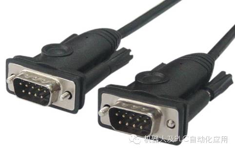
(2) DB-9:
In AT machines and later, the 20mA current loop interface is not supported, and the DB-9 connector is used, which connects to multifunction I/O cards or the COM1 and COM2 serial interfaces on motherboards. It only provides 9 signals for asynchronous communication. The pin assignment of the DB-9 connector is completely different from that of the DB-25 connector. Therefore, if connecting to a DCE device with a DB-25 connector, a special cable must be used.
Cable Length: When the communication rate is below 20kb/s, the maximum physical distance for direct connection with RS-232C is 15m (50 feet).
Maximum Direct Transmission Distance Explanation: The RS-232C standard stipulates that if a MODEM is not used, the maximum transmission distance between DTE and DCE is 15m (50 feet) under the condition that the symbol distortion is less than 4%. It can be seen that this maximum distance is given under the premise that the symbol distortion is less than 4%. To ensure that the symbol distortion is less than 4%, the interface standard specifies that the load capacitance of the driver should be less than 2500pF.