Click the blue text to followServo and Motion Control
Introduction to RS-232, RS-422, and RS-485
Overview of RS232
The RS-232 interface conforms to the interface standard for serial data communication established by the Electronic Industries Alliance (EIA), with the full original designation being EIA-RS-232 (abbreviated as 232 or RS232). It is widely used for connecting computer serial interface peripherals. The connecting cables and mechanical, electrical characteristics, signal functions, and transmission processes.
The data transmission rate specified by the RS-232-C standard is 50, 75, 100, 150, 300, 600, 1200, 2400, 4800, 9600, 19200 baud per second.
Characteristics of RS232:
RS-232 is one of the mainstream serial communication interfaces today. Due to the early emergence of the RS232 interface standard, it inevitably has shortcomings, mainly in the following four aspects:
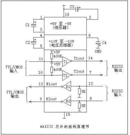
(1) The signal level values of the interface are relatively high, which can easily damage the chips of the interface circuit. The voltage of any signal line in the RS232 interface is in a negative logic relationship. That is: logic “1” is -3 to -15V; logic “0”: +3 to +15V, with a noise tolerance of 2V. This means that the receiver must recognize signals above +3V as logic “0” and signals below -3V as logic “1”. TTL levels are 5V for logic positive and 0 for logic negative. It is incompatible with TTL levels, so a level conversion circuit is required to connect with TTL circuits.
(2) The transmission rate is relatively low, with a bit rate of 20Kbps during asynchronous transmission; therefore, in the 51CPLD development board, the comprehensive program baud rate can only adopt 19200, which is also the reason.
(3) The interface uses one signal line and one signal return line to form a common ground transmission mode. This common ground transmission is prone to common-mode interference, making it weak against noise interference.
(4) The transmission distance is limited, with a maximum transmission distance standard value of 50 feet, but in practice, it can only be used for about 15 meters.

Overview of RS485
When communication distances require tens to thousands of meters, RS-485 serial buses are widely used. RS-485 employs balanced transmission and differential reception, thus having the ability to suppress common-mode interference. Additionally, the bus transceiver has high sensitivity, capable of detecting voltages as low as 200mV, allowing transmission signals to be recovered over kilometers.
RS-485 operates in half-duplex mode, meaning that only one point can be in sending state at any time, so the sending circuit must be controlled by an enable signal.
Characteristics of RS485:
RS-485 is very convenient for multipoint interconnection, allowing for the elimination of many signal lines. Using RS-485 can form a distributed system, allowing for a maximum of 32 drivers and 32 receivers to be connected in parallel. In response to the shortcomings of RS-232-C, the new standard RS-485 has the following characteristics:
(1) The electrical characteristics of RS-485: logic “1” is represented by a voltage difference of +2V to +6V between the two lines, while logic “0” is represented by a voltage difference of -6V to -2V between the two lines. The interface signal levels are lower than those of RS-232-C, making it less likely to damage the interface circuit chips, and this level is compatible with TTL levels, making it easier to connect with TTL circuits.
(2) The maximum data transmission rate is: 10Mbps.
(3) The RS-485 interface uses a combination of balanced drivers and differential receivers, which have strong common-mode interference capability, i.e., good noise immunity.
(4) The maximum transmission distance standard value for the RS-485 interface is 4000 feet, and in practice, it can reach 3000 meters.
(5) The RS-232-C interface only allows one transceiver to be connected on the bus, i.e., single-station capability; whereas the RS-485 interface can connect up to 128 transceivers on the bus, i.e., it has multi-station capability, allowing users to easily establish a device network using a single RS-485 interface.
Overview of RS422:
The full name of the RS-422 standard is “Electrical Characteristics of Balanced Voltage Digital Interface Circuits,” which defines the characteristics of the interface circuit. In fact, there is also a signal ground wire, making a total of five wires. Due to the high input impedance of the receiver and the stronger driving capability of the sending driver compared to RS232, multiple receiving nodes can be connected on the same transmission line, allowing for a maximum of 10 nodes. One master device (Master) and the rest are slave devices (Slave), with no communication allowed between slave devices, thus RS-422 supports point-to-multipoint bidirectional communication. The input impedance of the receiver is 4k, so the maximum load capacity of the sending end is 10×4k+100Ω (termination resistance).
The circuit principles of RS-422 and RS-485 are basically the same, both using differential transmission and reception without requiring a digital ground wire. The differential operation is the fundamental reason for the long transmission distance under the same rate conditions, which is the fundamental difference between both and RS232, as RS232 is single-ended input/output and requires at least a digital ground wire for duplex operation. The sending line and receiving line consist of three lines (asynchronous transmission), and additional control lines can be added to complete synchronous functions.
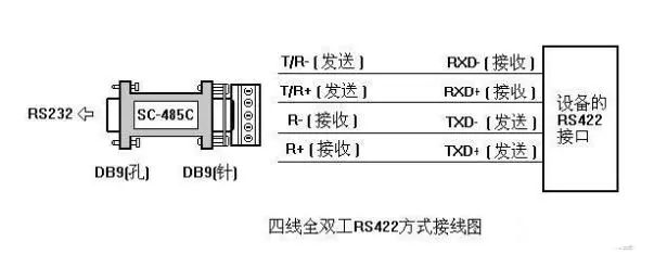
RS-422 can work in full duplex by using two pairs of twisted pairs without affecting each other’s reception and transmission, while RS485 can only work in half duplex, where sending and receiving cannot occur simultaneously, but it only requires one pair of twisted pairs. RS422 and RS485 can transmit 1200 meters at 19kpbs. With new type transceiver lines, devices can be connected.
The electrical performance of RS-422 is exactly the same as that of RS-485. The main difference is that RS-422 has four signal lines: two for sending (Y, Z) and two for receiving (A, B). Since the reception and transmission of RS-422 are separate, it can simultaneously receive and transmit (full duplex); RS-485 has two signal lines: one for sending and one for receiving.
Characteristics of RS422:
The four-wire interface of RS-422, due to the use of separate sending and receiving channels, does not require control of data direction, and any necessary signal exchange between devices can be done by software (XON/XOFF handshake) or hardware (a pair of separate twisted pairs). The maximum transmission distance of RS-422 is 4000 feet (approximately 1219 meters), and the maximum transmission rate is 10Mb/s. The length of the balanced twisted pair is inversely proportional to the transmission rate; the maximum transmission distance can only be achieved at rates below 100kb/s. The highest transmission rate can only be obtained at very short distances. Generally, the maximum transmission rate that can be achieved on a 100-meter-long twisted pair is only 1Mb/s.
RS-422 requires a termination resistor, with a resistance value approximately equal to the characteristic impedance of the transmission cable. In short-distance transmission, a termination resistor may not be required, generally within 300 meters. The termination resistor is connected at the farthest end of the transmission cable.
Differences Between RS-232, RS-422, and RS-485
1. RS232 is full duplex, RS485 is half duplex, and RS422 is full duplex.
2. RS485 and RS232 differ only in the physical communication protocol (i.e., interface standard); RS485 uses differential transmission while RS232 uses single-ended transmission, but there is not much difference in communication programs.
PCs are already equipped with RS232, which can be used directly. If RS485 communication is needed, simply connect an RS232 to RS485 converter to the RS232 port, without needing to modify the program.
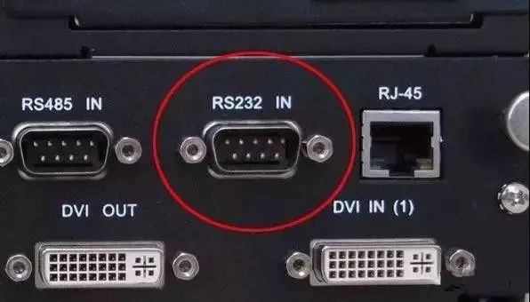
Are there any differences in the appearance of RS232 and RS485 interfaces?
Typically, the RS-232 interface appears in the form of 9 pins (DB-9) or 25 pins (DB-25). Most personal computers will have two sets of RS-232 interfaces, referred to as COM1 and COM2.
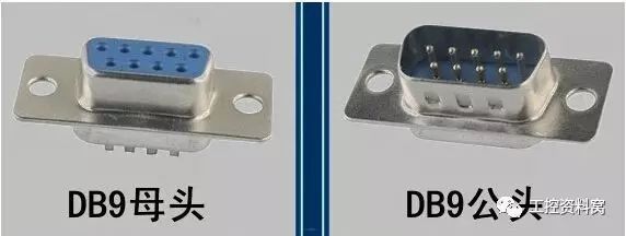
The connector uses a DB-25 type 25-pin socket. Some RS-232 interfaces connecting devices to PCs may only require three interface lines, namely “send data,” “receive data,” and “signal ground,” thus using a DB-9 type 9-pin socket, with transmission lines using shielded twisted pairs.
RS485 does not have a specific physical shape, and the interface is adopted based on the actual engineering situation.
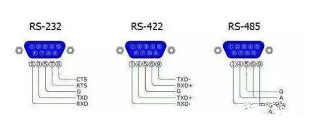
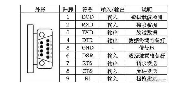
RS232 is the standard interface, with a D-shaped 9-pin head, and the signal definitions of the connected devices’ interfaces are the same. The signal definitions are as follows:
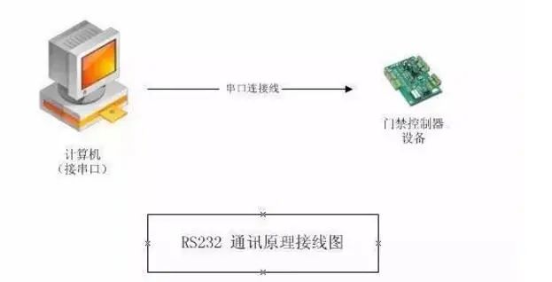
RS-232 only allows one-to-one communication (single-station capability).
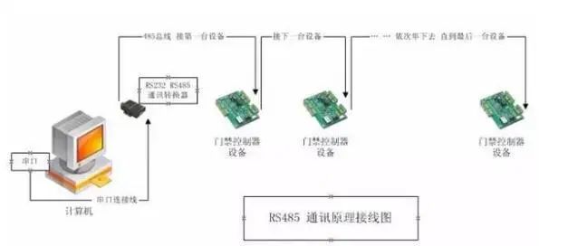
RS-485 interface allows up to 128 transceivers to be connected on the bus (multi-station capability).
Since PCs by default only come with RS232 interfaces, there are two ways to obtain RS485 circuits on the PC:
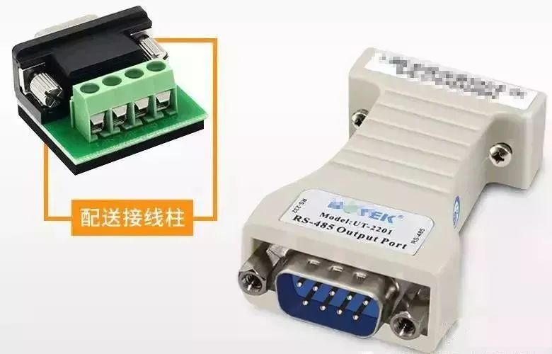
(1) By using an RS232/RS485 conversion circuit to convert the PC’s RS232 signal into RS485 signal. For more complex industrial environments, it is best to choose surge-proof products with isolation.
(2) By using a PCI multi-serial port card, one can directly select an expansion card that outputs RS485 type signals.
The computer connects to multiple 485 devices (access control controllers) through an RS232-RS485 converter, using a polling method to communicate with devices on the bus in turn.
The wiring markings are 485+ and 485-, corresponding to the linked device (controller) 485+ and 485-.
Communication Distance:The theoretical distance from the farthest device (controller) to the computer is 1200 meters; it is recommended that customers keep it within 800 meters, with the best effect within 300 meters. If the distance is too long, a 485 repeater (extender) can be purchased (please purchase from a professional converter manufacturer; the placement of the repeater in the bus should refer to the relevant manufacturer’s instructions). The repeater can theoretically extend to 3000 meters.
Load Quantity:This refers to how many devices (controllers) a single 485 bus can carry, which depends on the communication chip of the controller and the selection of the communication chip of the 485 converter. Generally, there are options for 32, 64, 128, and 256 devices; this is a theoretical number, and in actual applications, the load quantity may not meet the target due to environmental factors, communication distance, etc. The controllers and converters from Weigeng Company are designed for 256 devices, but it is actually recommended that customers keep the load on each bus within 80 devices.
The 485 communication bus (must use twisted pairs or one pair of network cables) if ordinary wires (non-twisted) are used, interference will be very significant, leading to communication issues or even failure to communicate.
Each controller device must be connected sequentially, without star connections or branches. If there are star connections or branches, interference will be very significant, leading to communication issues or even failure to communicate.
Popular Articles
ABB, Advantech, Siemens and Other 7 Giants Release Financial Reports
Discussing Mitsubishi J Series Servo Products “Illustrated Version”
Common Connection Ports and Communication Protocols for PLCs
Inertia: The Essence of Servo Systems
Schneider Electric Releases New Servo Products
Special Note: The materials for this article are sourced from the internet, representing only the views of the original author, with copyrights belonging to the original author! After the editor collects and organizes it, we share it with everyone for learning! If you believe that any content infringes your rights, please contact the editor! We will verify and make corrections immediately!