Follow our official account to receive timely updates on new articles.
Introduction:
RS-232, RS-485 and RS-422 are standards defined and published by the Electronic Industries Alliance (EIA). EIA is an American industry association focused on developing and promoting standards in the electronics and electrical industries. Among these, RS-485 is highly praised and widely used in industrial, medical, and consumer products, becoming a dominant specification for industrial interfaces.
Note: Some content in this article is excerpted from TI’s technical documentation.
RS-232
RS-232 links were originally used to support modem and printer applications on the IBM PC. However, this standard now supports communication with various peripherals and PCs.
1 Protocol/Standard:
- RS-232 complies with TIA-232 andEIA-232 standards.
- RS-232 covers three related areas: electrical, functional, and mechanical (i.e., connector form). The electrical specifications include definitions for the physical electrical layer standards.
- RS-232 is a single-ended point-to-point communication protocol (one transmitter and one receiver), where each data signal is transmitted along a single wire.
- Full-duplex communication allows for simultaneous data transmission and reception.
2 Typical Connections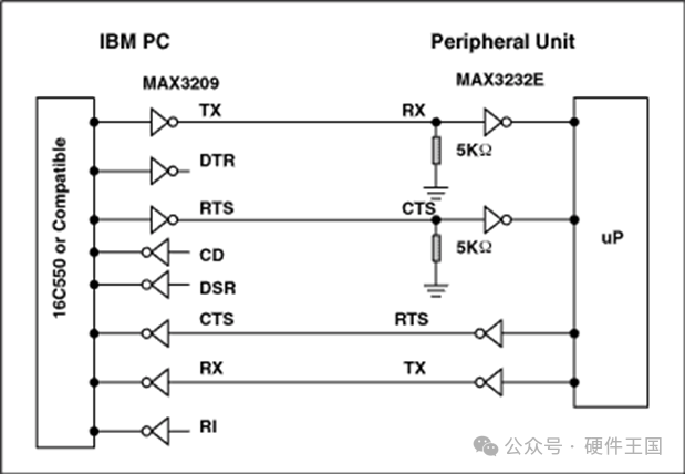
3 Level and Interface Standards:
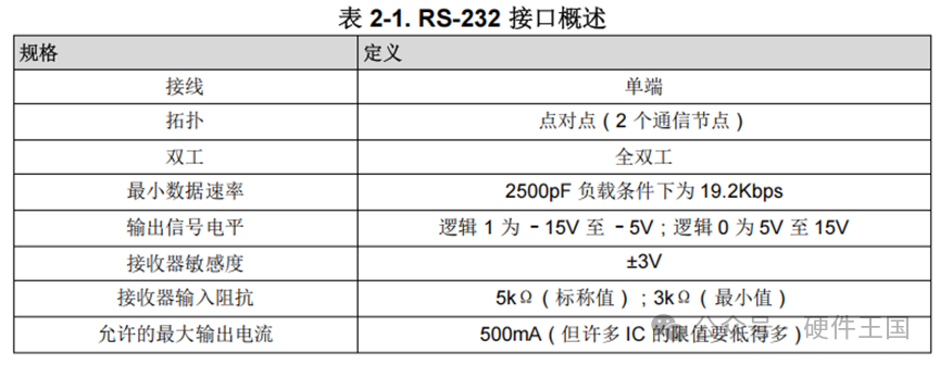
- The logic level of the transmitter for logic 1 is between –5V and –15V ; the logic level for logic 0 is between 5V and 15V .
- The transceiver must recognize voltages from –3V to –15V as logic 1, and voltages from 3V to 15V as logic 0 (receiver sensitivity ±3V).
- RS-232 transceivers can achieve data rates of up to 1Mbps.
4 Functional Overview
In addition to electrical specifications, RS-232 also includes functional definitions for 24 different signals; however, typically only 8 or fewer of these defined signals are used. This article covers the eight most commonly used signals in RS-232 which can be categorized into four different types: common signals (ground), data signals (TXD, RXD), timing signals (rarely used), and control signals (RTS, CTS, DTR, DSR, DCD, RI).
|
Signal Type |
Signal Name |
Functional Definition |
|
Data Signal |
TxD (Transmit Data) |
The data transmission line, where data is sent from the transmitter (e.g., computer) to the receiver (e.g., external device). |
|
RxD (Receive Data) |
The receiving data line, where the transmitter receives data sent from the receiver. |
|
|
Control Signal |
RTS (Request to Send) |
The request-to-send signal, indicating to the receiver that it is ready to receive data. |
|
CTS (Clear to Send) |
The clear-to-send signal, indicating to the transmitter that the receiver is ready to receive data. |
|
|
DTR (Data Terminal Ready) |
The data terminal ready signal, indicating that the communication device is ready to receive data. |
|
|
DSR (Data Set Ready) |
The data set ready signal, indicating that the other device is ready to receive data. |
|
|
DCD (Data Carrier Detect) |
The data carrier detect signal (presence detection signal), indicating that there is a valid connection between the sending and receiving devices. |
|
|
RI (Ring Indicator) |
The ring indicator signal, typically used to indicate that there is ringing on the communication line. |
|
|
Common Signal |
GND (Ground) |
The ground line, used to connect the grounds of all devices. |
Note:
1) Although both nodes send and receive data, the TxD and RxD lines depend on the host node in the system rather than the peripherals. Communication is initiated by the host (master).
2) In applications requiring some form of handshake, a common use case is to use two data signals + two control signals. These control signals are “Request to Send” (RTS) and “Clear to Send” (CTS) signals. When the DTE (acting as the host and controller data terminal device) is ready to send data via the TxD signal to the DCE (acting as the host and controller peripheral data communication device), the RTS signal will be activated; when the RTS signal is received and the peripheral notifies the host that it is ready to receive data, the CTS signal will be activated. However, this simple version of handshake is not the only common handshake signal used when employing systems like RS-232 and modems. Modems typically add four additional control signals on top of RTS and CTS . In addition to RTS and CTS , common control signals also include Data Terminal Ready (DTR), Data Set Ready (DSR), Data Carrier Detect (DCD) and Ring Indicator (RI) signals.DTE sends the DTR signal to the DCE, indicating that it is ready to send or receive data; upon receiving the DTR signal, the DCE sends the DSR signal back to the DTE, indicating that it is connected to the communication line.DCD signal is sent from the DCE to the DTE to indicate that there is a valid connection between the DTE and DCE. Finally, the RI signal is sent from the DCE to the DTE to indicate that there is ringing on the communication line, or simply put, the DCE wishes to communicate with the DTE itself, to which the DTE responds by sending the DTR signal.
3) Regarding the mechanical interface of RS-232, two commonly used connectors are DB25 and DB9S. DB25 connectors allow each RS-232 functional signal to have a connection point. The more common DB9S connector supports the eight most common RS-232 functional signals (as mentioned above) along with a common ground connection.
RS-485
1 Protocol/Standard:
- RS-485 is merely an electrical standard. Compared to a complete interface standard that defines functional, mechanical, and electrical specifications, it only defines the electrical characteristics of drivers and receivers using balanced multipoint transmission lines.
- RS-485 is a differential signal serial communication protocol that allows for multi-node communication, making it very suitable for multipoint communication networks.
- Half-duplex or full-duplex: It supports half-duplex communication (only one can send or receive at the same time) but can also support full-duplex communication with additional lines.
- Data transmission rates can reach up to 10 Mbps, suitable for long-distance, high-speed transmission.
2 Main Features
- Balanced interface
- Multipoint using a single 5V power supply
- –7V to +12V common mode range of the bus
- Up to 32 unit loads
- 10Mbps maximum data rate (distance of 40 feet)
- 4000 feet maximum cable length (at a rate of 100kbps)
3 Network Topology:
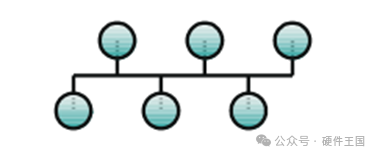
RS-485 standard recommends using a daisy chain to connect its nodes, also known as shared line or bus topology. In this topology, the drivers, receivers, and transceivers used are connected to the trunk line via small branches (stub). The interface bus can be designed for full-duplex or half-duplex transmission.
Full-duplex implementation requires two signal pairs (four wires) and full-duplex transceivers, which have separate bus access lines for the transmitter and receiver. Full-duplex mode allows nodes to send data on one pair while receiving data on another pair.
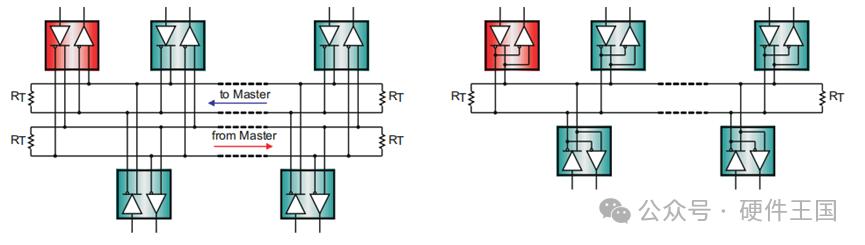 In half-duplex mode, only one pair of signals is used, and data must be driven and received at different times. Both implementations require control signals (such as driver/receiver enable signals) to manage all nodes, ensuring that only one driver is active on the bus at any time. Multiple drivers accessing the bus simultaneously can lead to bus contention, which must be avoided through software control at all times.
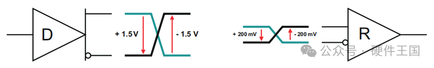
4 Level Standards:
Drivers compliant with the RS-485 standard can provide a differential output of no less than 1.5V on a 54Ω load, while compliant receivers can detect differential inputs as low as 200mV . Even with significant signal attenuation in cables and connectors, these two values still provide ample margin for reliable data transmission. This robustness is a primary reason why RS-485 is very suitable for long-distance networking in noisy environments.
5 Bus Termination and Stub Length:
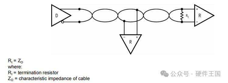
To avoid signal reflections, data transmission lines should always be terminated, and stubs should be as short as possible. Proper termination requires that the termination resistance RT matches the characteristic impedance of the transmission cable Z0 . The RS-485 standard recommends using cables with Z0 = 120Ω, so the cable trunk is typically terminated with a 120Ω resistor at each end.
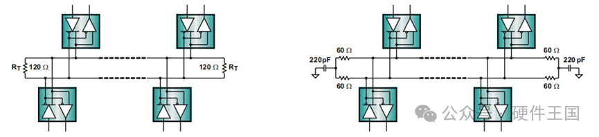 In noisy environments, it is common to replace the 120Ω resistor with two 60Ω resistors, forming a low-pass filter to provide additional common-mode noise filtering capability. It is essential to match the resistor values (preferably using 1% tolerance resistors) to ensure that both filters have equal frequency roll-off. A larger resistor tolerance (i.e., 20%) will result in different cutoff frequencies for the filters, and common-mode noise will convert to differential noise, reducing the receiver’s immunity to interference.
6 Failure Protection:
Failure protection allows the receiver to output a defined state in the absence of an input signal.
There are three possible causes for loss of signal (LOS):
1. Open Circuit: Cable interruption or transceiver disconnection from the bus
2. Short Circuit: Wires in the differential pair contact each other due to insulation failure
3. Bus Idle: This occurs when all bus drivers are inactive.
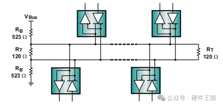
Under the above conditions, when the input signal is zero, traditional receivers would output a random state; however, modern transceivers include a bias circuit that can protect against open circuits, short circuits, and bus idle conditions, ensuring that even when the signal is lost, the receiver can force an output to a defined state. External failure protection circuits consist of a resistor divider that can generate sufficient bus differential voltage to drive the receiver to produce a defined output state. To ensure sufficient noise margin, in addition to the 200mV receiver input threshold, VAB must also include the maximum measured differential noise, VAB = 200mV + V noise.
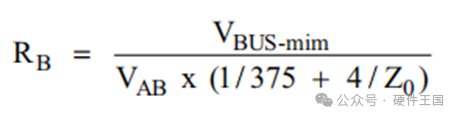
The minimum bus voltage is 4.75V, (5V – 5%), VAB = 0.25V and Z0 = 120Ω, then RB is 528Ω. Insert two 523Ω in series into RT .
7 Grounding and Isolation:
When designing remote data links, designers must assume significant ground potential differences (GPD). These voltages Vn can superimpose on the transmission line as common-mode interference. Even if the total superimposed signal is within the common-mode range of the receiver input, relying on local grounding as a reliable current return path is very risky.
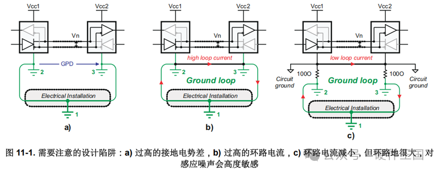 Since remote nodes may draw power from different parts of the electrical device, modifications to such devices (i.e., during maintenance work) can cause ground potential differences to exceed the common-mode range of the receiver input. Therefore, a data link that works fine today may stop functioning at some point in the future. It is also recommended not to directly connect the remote ground via a ground wire (see the above figureb), as large loop ground currents can introduce common-mode noise onto the signal line.
To directly connect remote ground, RS485 standard recommends isolating the device ground from the local system ground by inserting resistors (see the above figurec). Although this method reduces loop currents, the presence of large loop grounds still makes the data link sensitive to noise generated somewhere along the loop. Therefore, a robust data link has yet to be established.
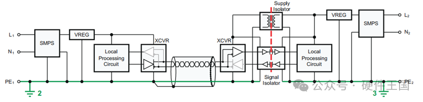
A robust RS-485 data link method that can tolerate thousands of volts of ground potential difference and is suitable for long-distance transmission is to isolate the signal and power supply (see the diagram below). In this case, power isolators (such as isolated DC/DC converters) and signal isolators (such as digital capacitive isolators) can prevent current from flowing between remote system grounds and avoid generating loop currents.
 RS-422
RS-422 was introduced to overcome the limitations of single-ended signal standards like RS-232, which lacks common-mode noise suppression and typically limits data rates to below 0.5 Mbps. RS-422 interfaces can overcome these limitations.
1 Protocol/Standard:
- RS-422 is very similar to RS-485, but there are some differences between the two, including the output stage of the driver, the common-mode range of the interface, the input resistance of the receiver, and the driving capability of the driver.
- RS-422 is typically full-duplex, meaning that data can be sent and received simultaneously.
- Data transmission rates are higher, reaching up to 10 Mbps. RS-422 outperforms RS-485 in high-speed transmission.
2 Main Features
- Balanced interface
- –7V to +7V common mode range of the bus
- Up to 10 unit loads (4 kΩ to circuit common is one unit load)
- 10Mbps maximum data rate (distance of 40 feet)
3 Network Topology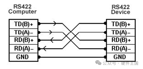
1), Point-to-Point Configuration: A point-to-point system consists of one driver and one receiver. Point-to-point applications can be viewed as single-ended standards like TIA/EIA-232.
2), One Driver Multi-Point Configuration: One driver connects to two or more receivers, typically in a daisy chain manner. For RS-422, if the input impedance of the receiver (RIN) equals 4 kΩ or one unit load, the maximum number of receivers is 10. If the receiver’s RIN equals 8 kΩ, that receiver counts as half a unit load. Therefore, an RS-422 driver capable of driving 10 unit loads can drive 20 receivers with RIN = 8 kΩ.
4 Level Standards
The standard RS-422 drivers guarantee to provide and absorb at least 20 mA of current at a 100 Ω load. This corresponds to a minimum differential output voltage (VOD) of 2 V.
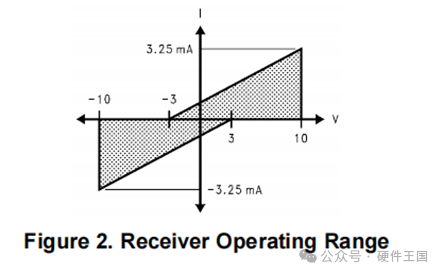
Complementary RS-422 receivers must equal or be less than one unit load (4 kΩ to circuit common is one unit load). The operating range of the receiver is defined between ±10 V, as shown in the shaded area in the diagram below.
RS-422 receivers have a threshold of ±200 mV across the entire common-mode range (±7 V). The differential output swing of the driver guarantees a differential noise margin of ≥1.8 V between the receiver’s threshold.
5 Bus Termination and Stub Length
Transmission line termination matching is an important factor that designers must consider when transmitting electrical signals from point A to point B. Signals can be terminated in many different ways, using parallel termination (as illustrated in the diagram below) as an example.
Parallel termination is a very popular termination matching method that allows for higher data rates and longer cable lengths than other termination schemes, as transmission line effects are minimized. This is achieved by selecting a termination resistance (Rt) that closely matches the cable impedance (ZO). Cable impedance can be obtained from the cable manufacturer or measured using time-domain reflectometry (TDR techniques. Additionally, since transmission line effects are minimized, good signal quality can also be achieved in multipoint configurations as long as the branches (discussed later) themselves are not transmission lines.
One disadvantage of parallel termination is the high power consumption associated with heavy termination loads. This also results in smaller differential output voltages and lower DC noise margins compared to series termination.
To avoid signal reflections, data transmission lines should always be terminated, and stubs should be as short as possible. Proper termination requires that the termination resistance RT matches the characteristic impedance of the transmission cable Z0 . Since RS-422 is a multipoint standard, receivers can be connected to the bus via branches. The length of the branches is important as it can affect the signal. As the branch length increases, its characteristics begin to behave like a transmission line. When is a branch considered a transmission line? Here are typical guidelines for branches and transmission lines: Time domain: If the propagation delay of the branch (one way) is greater than 1/8 of the signal transition time (from 0% to 100% of the signal transition), then the branch can be considered a transmission line.
Furthermore, the maximum length of the branch depends on the transition time measured at the branch connection point. This is very important because if the total length of the cable is 1000 feet, then a cable hanging at a distance of 750 feet from the driver can have a longer branch than one at a distance of 75 feet from the driver. This is because the cable capacitance slows down the transition time of the driver’s output, and as the signal propagates along the cable, the transition time becomes longer. The length of the branch can be increased by slowing down the transition edges at the branch connection point. This can be achieved using large capacitive loads or RS-422 drivers with output waveform control (such as TI‘s DS3691, DS3692 or DS36C280) to achieve.
6 Failure Protection
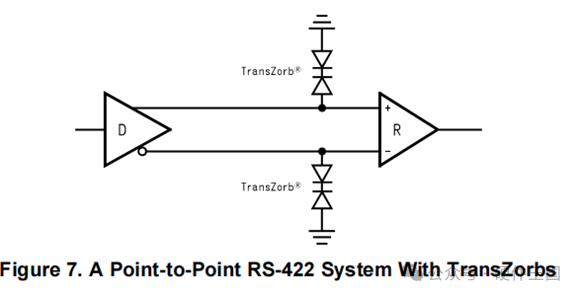
Similar to RS-485, typical RS-422 interfaces consider open circuit, terminated, and short-circuit inputs as three types of fault safety (see the diagram below). Receivers with complete fault safety protection can guarantee stable output states under all three fault safety conditions.
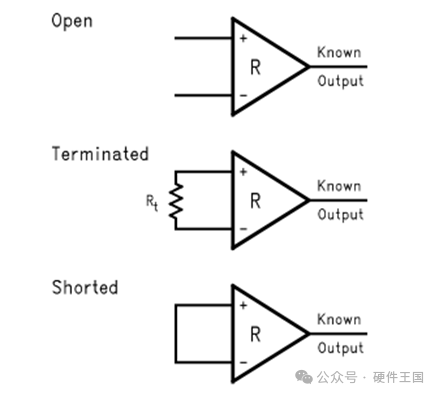
Open circuit fault: The receiver can provide open circuit input fault protection through internal pull-up and pull-down resistors (typically >50 kΩ). Sometimes, a bias resistor is used on one input, while the other input is biased to a voltage reference point. Any receiver without built-in fault safety features can use external pull-up and pull-down resistors to provide fault safety protection.
Short circuit fault: This occurs when the inputs of the receiver are shorted together. If the receiver does not have this type of fault protection, merely using external pull-up and pull-down resistors may not help; the “alternate-failsafe” terminal technique is required:
When the receiver’s input is in a terminated condition, the receiver capable of determining its output has terminal fault safety.
Key Metrics Summary
|
RS232 Key Metrics Summary |
|||
|
Parameter |
Condition |
Minimum |
Maximum |
|
Output voltage of the driver in open circuit condition |
25V |
||
|
Output voltage of the driver under load |
3kΩ < RL < 7kΩ |
±5V |
±15V |
|
Voltage change rate |
4V |
30v/us |
|
|
Maximum load capacitance |
2500pf |
||
|
Receiver input resistance |
3K |
7K |
|
|
Logic1 |
-3V |
||
|
Logic0 |
3V |
|
RS422 Key Metrics Summary |
|||
|
Parameter |
Condition |
Minimum |
Maximum |
|
Output voltage of the driver in open circuit condition |
±10V |
||
|
Output voltage of the driver under load |
RL =100Ω |
±2V |
±10V |
|
Driver output resistance |
A to B |
100 |
|
|
Driver output short-circuit current |
Output to common connection (GND) |
150mA |
|
|
Driver common-mode voltage |
RL =100Ω |
±3V |
|
|
Receiver sensitivity |
VCM < ±7V |
±200mv |
|
|
Receiver common-mode voltage range |
-7 |
+7V |
|
|
Receiver input impedance |
4K |
||
|
Differential receiver voltage |
Operational |
±10V |
|
|
Can withstand |
±12V |
|
RS485 Key Metrics Summary |
|||
|
Parameter |
Condition |
Minimum |
Maximum |
|
Output voltage of the driver in open circuit condition |
±1.5V |
±6V |
|
|
Output voltage of the driver under load |
RL =100Ω |
±1.5V |
±5V |
|
Driver output resistance |
|||
|
Driver output short-circuit current |
Output to common connection (GND) |
±250mA |
|
|
Driver common-mode voltage |
RL =54Ω |
±3V |
|
|
Receiver sensitivity |
-7V < VCM < 12V |
±200mv |
|
|
Receiver common-mode voltage range |
-7 |
+12V |
|
|
Receiver input impedance |
12K |

(If you like this article, scan the code to follow us)
Note: Please indicate the source when reprinting
Recommended classic articles from this collection:
05_Mastering the Basic Applications of the SD Protocol
04_Mastering the SPI Protocol and Flash Memory Structure
03_JTAG – Boundary Scan Technology
02_Mastering the I2C Protocol and Applications
01_UART Serial Protocol