**Introduction** In many industrial and automotive applications, protecting interface transceivers from various electrical overstress events is a major concern. Transient Voltage Suppressor (TVS) diodes are commonly used for this purpose as they clamp voltage spikes by creating a low impedance current path.
The electrical characteristics of TVS diodes are determined by several process factors. These parameters relate to the TVS voltage, current, and power ratings, with a variety of values to fit different applications. However, selecting the right device is not straightforward, as one can find by looking at the component datasheets. In this article, I will discuss the voltage parameters and demonstrate which TVS diodes are suitable for RS-232, RS-485, and Controller Area Network (CAN) applications. Of course, peak pulse power dissipation and peak pulse current are also critical parameters that determine the discharge capability and Electrostatic Discharge (ESD) levels in the system, but here I will focus on voltage.
**TVS Voltage Parameters VWM, VBR, and VC**
When unwanted high-voltage transients occur, TVS diodes should clamp the voltage; they should also be “transparent” when the transceiver operates under normal conditions. Therefore, the first parameter to check on the datasheet is the rated standoff voltage VWM. VWM, also known as the rated working voltage, indicates that below this voltage, the TVS is open-circuit with low standby leakage current.
When selecting, you want VWM to be greater than the recommended transceiver operating region. As the input voltage increases, the TVS begins to breakdown and conducts more current at VBR. More importantly, the maximum voltage parameter VC, which is the clamping voltage under high current pulse conditions, is critical. VC indicates the maximum clamping voltage at a specific pulse current. When comparing VC with the transceiver parameters, you need to ensure that it does not exceed the absolute maximum rating of the integrated circuit (IC). The “absolute maximum” is the maximum voltage limit that the transceiver is allowed at any time. Any voltage above this limit will put the transceiver in an unsafe operating region and may lead to complete failure.
**Example: TVS Selection for RS-232, RS-485, and CAN Transceivers**
I will introduce several example devices for RS-232, RS-485, and CAN transceivers and their corresponding TVS diodes. I have gathered the relevant parameters from their respective datasheets, and I hope to illustrate how different components work together by presenting these parameter values.
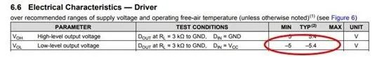
TI’s MAX3232 is a common RS-232 transceiver with two transmitters and two receivers. In Figures 1 and 2, I highlight two important parameters: a working voltage of ±5.4V and an absolute maximum driver output voltage of ±13.2V. According to the RS-232 standard, the signal swing should be above ±5V. Here, you can allow some margin.
Figure 1: MAX3232 Driver Working Voltage
Figure 2: MAX3232 Driver Absolute Maximum Ratings
The TVS diode suitable for MAX3232 is Bourns’ SMBJ8.0CA. In Figure 3, you can see that the peak reverse working voltage is 8V, and the maximum clamping voltage is 13.6V.
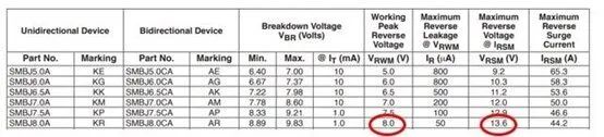 Figure 3: SMBJ8.0CA Peak Reverse Working Voltage and Maximum Clamping Voltage
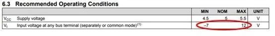
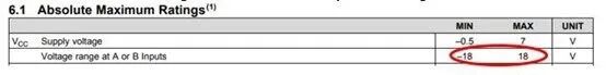
Next, let’s look at the 8-pin RS-485 transceiver, TI’s THVD1500. According to the RS-485 standard, RS-485 transceivers can operate over a wide common mode range (-7V to 12V) (Figure 3). As shown in Figure 4, the absolute maximum voltage for the THVD1500 bus pins is ±18V.
Figure 4: THVD1500 Driver Working Voltage
Figure 5: THVD1500 Driver Absolute Maximum Ratings
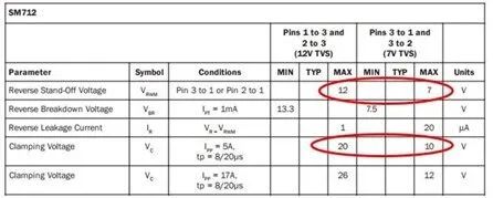
SM712 is a common TVS diode used for RS-485 applications. This TVS features an asymmetric reverse standoff voltage that matches the common mode operating range of RS-485 applications. Additionally, its clamping voltage is close to the limits of TI’s THVD1500, as shown in Figure 6.
Figure 6: SM712 Reverse Standoff Voltage and Clamping Voltage
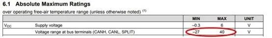
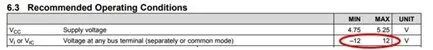
Last but not least, the TI SN65HVD1040A 8-pin CAN transceiver has a relatively high absolute maximum voltage (Figure 7), which simplifies the TVS selection. Similar to RS-485, the CAN bus can also tolerate some common mode voltage variations (Figure 8).
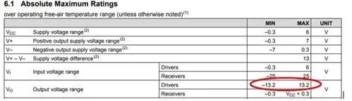
Figure 7: SN65HVD1040A Driver Absolute Maximum Ratings
Figure 8: SN65HVD1040A Driver Working Voltage
Considering all factors, Bourns’ CDSOT23-T24CAN is a suitable device for SN65HVD1040A. This device offers a reverse working voltage of 24V and a clamping voltage of 36V to 40V. For space-saving purposes, I have not copied the datasheet here. However, I believe that based on the first two examples, finding the relevant parameters should not be too difficult.
Similarly, the voltage parameters are just part of the electrical characteristics of TVS devices, but they are the primary considerations when selecting a TVS. To better understand the full characteristics of TVS devices, you should also consider other parameters such as peak power and peak current.
Welcome to follow “Must-Learn Classroom”:Here you can get EMC learning materials, tips, project cases, and various information! Master the insights and reduce the difficulties brought by EMC R&D costs. Generally, the R&D costs related to EMC mainly reflect in three aspects:
1) Increased development rounds due to design modifications resulting from EMC tests failing, ultimately increasing development costs that include not only time but also human and material resources;
2) Design or unnecessary component costs due to inaccurate grasp of EMC technology;
3) Testing costs arising from repeated tests.
When rectifying products for EMC, one should first consider the differences between individual product rectifications and mass production. Generally, during EMC rectification, every part of the product will be carefully adjusted, and the countermeasures and components used are selected repeatedly. However, in mass production, due to assembly line operations, it is difficult to adjust each part of the product carefully, and combined with the batch discreteness of the components used, the EMC performance of mass-produced products can vary significantly. Only by leaving enough margin for this difference during product rectification can we ensure that the EMC compliance standards of mass-produced products are met. If the consistency of the production process is well controlled, and the consistency of the components used is good, while considering the uncertainty of laboratory testing equipment, a margin of at least 4dB for conducted interference rectification and at least 6dB for radiated interference rectification is recommended. If the factory’s production process consistency control is not particularly good (for example, mainly manual or semi-manual operations rather than computer-controlled automated operations), and the discreteness of the components used is large, it is suggested to increase the margin by at least another 3dB.
If necessary, samples of at least three products from the batch produced after EMC rectification can be extracted for relevant project testing to determine whether they all meet the standard requirements and how the results vary, and whether they comply with the criteria for determining compliance with standards for batch product testing. If they all pass, it can be concluded that the rectification measures are appropriate and effective.
For common electromagnetic compatibility issues, comprehensive application of the following rectification measures generally can solve most problems:
Strengthen shielding and reduce gaps: conductive glue can be applied at the assembly face of the shield, or conductive gaskets can be added at the assembly face, or even conductive metal tape can be used as a remedy.
Conductive gaskets can be woven metal wire, soft metals (copper, lead, etc.) that are easy to shape, rubber with a metal layer, conductive rubber, or comb spring contact fingers, etc.
Layout and Wiring Issues:
Properly adjust the layout between internal components of the device, cable routing, and arrangement to minimize the mutual influence of different types of components and cables without affecting performance.
Strengthen grounding performance and reduce grounding resistance;
A separate low-impedance grounding should be provided for the entire device.
Strengthen filtering of interfaces and connections between metal enclosures and shielding layers;
Improve or add filters on the power supply and signal input/output lines of the device.
Correctly select transmission cables; ensure the shielding layer of the cables is properly grounded;
Change ordinary small signal or high-frequency signal cables to shielded cables; change ordinary low-frequency, high-current signal or data transmission signal cables to twisted pair cables.
Shield and isolate important components, boards, and devices, such as adding well-grounded metal isolation chambers or small shielding covers.
Circuit and Power Supply Issues:
Improve or add filtering to the power supply and circuits to bypass high-frequency interference.
Figure 3: SMBJ8.0CA Peak Reverse Working Voltage and Maximum Clamping Voltage
Next, let’s look at the 8-pin RS-485 transceiver, TI’s THVD1500. According to the RS-485 standard, RS-485 transceivers can operate over a wide common mode range (-7V to 12V) (Figure 3). As shown in Figure 4, the absolute maximum voltage for the THVD1500 bus pins is ±18V.
Figure 4: THVD1500 Driver Working Voltage
Figure 5: THVD1500 Driver Absolute Maximum Ratings
SM712 is a common TVS diode used for RS-485 applications. This TVS features an asymmetric reverse standoff voltage that matches the common mode operating range of RS-485 applications. Additionally, its clamping voltage is close to the limits of TI’s THVD1500, as shown in Figure 6.
Figure 6: SM712 Reverse Standoff Voltage and Clamping Voltage
Last but not least, the TI SN65HVD1040A 8-pin CAN transceiver has a relatively high absolute maximum voltage (Figure 7), which simplifies the TVS selection. Similar to RS-485, the CAN bus can also tolerate some common mode voltage variations (Figure 8).
Figure 7: SN65HVD1040A Driver Absolute Maximum Ratings
Figure 8: SN65HVD1040A Driver Working Voltage
Considering all factors, Bourns’ CDSOT23-T24CAN is a suitable device for SN65HVD1040A. This device offers a reverse working voltage of 24V and a clamping voltage of 36V to 40V. For space-saving purposes, I have not copied the datasheet here. However, I believe that based on the first two examples, finding the relevant parameters should not be too difficult.
Similarly, the voltage parameters are just part of the electrical characteristics of TVS devices, but they are the primary considerations when selecting a TVS. To better understand the full characteristics of TVS devices, you should also consider other parameters such as peak power and peak current.
Welcome to follow “Must-Learn Classroom”:Here you can get EMC learning materials, tips, project cases, and various information! Master the insights and reduce the difficulties brought by EMC R&D costs. Generally, the R&D costs related to EMC mainly reflect in three aspects:
1) Increased development rounds due to design modifications resulting from EMC tests failing, ultimately increasing development costs that include not only time but also human and material resources;
2) Design or unnecessary component costs due to inaccurate grasp of EMC technology;
3) Testing costs arising from repeated tests.
When rectifying products for EMC, one should first consider the differences between individual product rectifications and mass production. Generally, during EMC rectification, every part of the product will be carefully adjusted, and the countermeasures and components used are selected repeatedly. However, in mass production, due to assembly line operations, it is difficult to adjust each part of the product carefully, and combined with the batch discreteness of the components used, the EMC performance of mass-produced products can vary significantly. Only by leaving enough margin for this difference during product rectification can we ensure that the EMC compliance standards of mass-produced products are met. If the consistency of the production process is well controlled, and the consistency of the components used is good, while considering the uncertainty of laboratory testing equipment, a margin of at least 4dB for conducted interference rectification and at least 6dB for radiated interference rectification is recommended. If the factory’s production process consistency control is not particularly good (for example, mainly manual or semi-manual operations rather than computer-controlled automated operations), and the discreteness of the components used is large, it is suggested to increase the margin by at least another 3dB.
If necessary, samples of at least three products from the batch produced after EMC rectification can be extracted for relevant project testing to determine whether they all meet the standard requirements and how the results vary, and whether they comply with the criteria for determining compliance with standards for batch product testing. If they all pass, it can be concluded that the rectification measures are appropriate and effective.
For common electromagnetic compatibility issues, comprehensive application of the following rectification measures generally can solve most problems:
Strengthen shielding and reduce gaps: conductive glue can be applied at the assembly face of the shield, or conductive gaskets can be added at the assembly face, or even conductive metal tape can be used as a remedy.
Conductive gaskets can be woven metal wire, soft metals (copper, lead, etc.) that are easy to shape, rubber with a metal layer, conductive rubber, or comb spring contact fingers, etc.
Layout and Wiring Issues:
Properly adjust the layout between internal components of the device, cable routing, and arrangement to minimize the mutual influence of different types of components and cables without affecting performance.
Strengthen grounding performance and reduce grounding resistance;
A separate low-impedance grounding should be provided for the entire device.
Strengthen filtering of interfaces and connections between metal enclosures and shielding layers;
Improve or add filters on the power supply and signal input/output lines of the device.
Correctly select transmission cables; ensure the shielding layer of the cables is properly grounded;
Change ordinary small signal or high-frequency signal cables to shielded cables; change ordinary low-frequency, high-current signal or data transmission signal cables to twisted pair cables.
Shield and isolate important components, boards, and devices, such as adding well-grounded metal isolation chambers or small shielding covers.
Circuit and Power Supply Issues:
Improve or add filtering to the power supply and circuits to bypass high-frequency interference.

This content is compiled by “Teacher Lv Yang” from the WeChat public account “Must-Learn Classroom”. For any feedback, please leave us a message.
Follow the Electromagnetic Compatibility (EMC) WeChat public account to receive content related to electromagnetic compatibility. Search the public account “EMC_EMI” in WeChat or scan the QR code on the left below;
Join the Electromagnetic Compatibility (EMC) WeChat group for real-time technical exchanges and discussions with hundreds of EMC peers from home and abroad. Add WeChat ID “yzg3369” as a friend or scan the middle QR code below, and note “EMC” to be invited to join;
Join the Electromagnetic Compatibility (EMC) QQ group for real-time technical exchanges and discussions with thousands of EMC peers from home and abroad. Add QQ number “34013334” or scan the right QR code below, and note “EMC” to be invited to join.
For original technical article submissions or recommendations for reprinting technical articles, contact Engineer Lv (WeChat: mythball), QR code on the left below;
For training agency recruitment, mutual publicity cooperation, and business promotion, contact Engineer Wang (WeChat: wangshaoqi96), QR code on the right below.
|

Engineer Lv
|

Engineer Wang
|
Electromagnetic Environment Effect Industry Technology Innovation Alliance Media Matrix: