1. RS-232
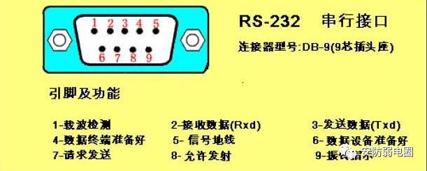
RS-232-C is a serial physical interface standard established by the Electronic Industry Association (EIA) in the United States. RS stands for “Recommended Standard,” 232 is the identification number, and C indicates the revision number. Its full name is “Serial binary data exchange interface technology standard between Data Terminal Equipment (DTE) and Data Communication Equipment (DCE).” This standard specifies the use of a 25-pin DB-25 connector, detailing the signal content for each pin and the voltage levels for various signals. Later, IBM simplified RS-232 to a DB-9 connector, which became the de facto standard. In industrial control, the RS-232 port typically uses only three lines: RXD (2), TXD (3), and GND (5).
The RS-232-C bus standard has 25 signal lines, including a main channel and an auxiliary channel. In most cases, the main channel is primarily used, and for general duplex communication, only a few signal lines are needed, such as one for sending, one for receiving, and one for ground.
The data transmission rates specified by the RS-232-C standard are 50, 75, 100, 150, 300, 600, 1200, 2400, 4800, 9600, 19200 baud per second.

The RS-232-C standard allows a driver to have a capacitive load of 2500pF, and the communication distance is limited by this capacitance. For example, using a communication cable with 150pF/m capacitance, the maximum communication distance is 15m; if the capacitance per meter of the cable is reduced, the communication distance can be increased. Another reason for the short transmission distance is that RS-232 uses single-ended signal transmission, which suffers from common ground noise and cannot suppress common-mode interference, thus it is generally used for communication within 20m.
1. Characteristics of the RS-232-C Interface Standard:
-
(1)Uses negative logic, where logic “1” is -15V to -5V, and logic “0” is +5V to +15V.
-
(2)Uses full-duplex mode.
2. Due to the early emergence of the RS-232 interface standard, it inevitably has some shortcomings, mainly as follows:
-
(1)The signal voltage levels of the interface are relatively high, which can damage the interface circuit chips. Additionally, because it is not compatible with TTL levels, a level conversion circuit is required to connect with TTL circuits.
-
(2)The transmission rate is relatively low, with a baud rate of 20Kbps during asynchronous transmission. Now, with the use of new UART chips like the 16C550, baud rates can reach 115.2Kbps.
-
(3)The interface uses one signal line and one signal return line to form a common ground transmission method, which is susceptible to common-mode interference, resulting in weak noise immunity.
-
(4)The transmission distance is limited, with a maximum standard transmission distance of 50 meters, but in practice, it can only be used for about 15 meters.
-
(5)RS-232 only allows point-to-point communication, while the RS-485 interface allows up to 128 transceivers to be connected on the bus.

2. RS-485
RS-485 serial bus is widely used when communication distances range from several dozen meters to thousands of meters. RS-485 uses balanced transmission and differential reception, which provides the ability to suppress common-mode interference. Additionally, the bus transceiver has high sensitivity, capable of detecting voltages as low as 200mV, allowing the transmission signal to be recovered over kilometers.

RS-485 operates in half-duplex mode, meaning that only one point can be in the sending state at any time, thus the sending circuit must be controlled by an enable signal.
RS-485 is very convenient for multipoint interconnection, allowing many signal lines to be saved. By using RS-485, a distributed system can be formed, allowing up to 32 drivers and 32 receivers to be connected in parallel.
In response to the shortcomings of RS-232-C, the new standard RS-485 has the following characteristics:
-
(1)The electrical characteristics of RS-485: logic “1” is represented by a voltage difference of +2V to +6V between the two lines, and logic “0” is represented by a voltage difference of -6V to -2V. The signal voltage levels of the interface are lower than those of RS-232-C, making it less likely to damage the interface circuit chips, and this level is compatible with TTL levels, facilitating connection with TTL circuits.
-
(2)The maximum data transmission rate is 10Mbps.
-
(3)The RS-485 interface uses a combination of balanced drivers and differential receivers, providing strong common-mode interference immunity, i.e., good noise performance.
-
(4)The maximum standard transmission distance for RS-485 is 4000 feet, and in practice, it can reach up to 3000 meters.
-
(5)The RS-232-C interface only allows one transceiver to be connected on the bus, i.e., single-station capability; while the RS-485 interface allows up to 128 transceivers to be connected on the bus, i.e., multi-station capability, allowing users to easily establish a device network using a single RS-485 interface.

3. RS-422
The circuit principles of RS-422 and RS-485 are fundamentally the same, both using differential transmission and reception, and do not require a digital ground line. The differential operation is the fundamental reason for the longer transmission distance under the same rate conditions, which is the main difference between them and RS-232, as RS-232 is single-ended input/output and requires at least three lines (digital ground, sending line, and receiving line) for duplex operation (asynchronous transmission), along with additional control lines for synchronization and other functions.

RS-422 can operate in full-duplex mode using two pairs of twisted pairs, allowing simultaneous sending and receiving without interference, while RS-485 can only operate in half-duplex mode, meaning sending and receiving cannot occur simultaneously, but it only requires one pair of twisted pairs. RS-422 and RS-485 can transmit 1200 meters at 19kbps. With new transceiver lines, multiple devices can be connected.
The electrical performance of RS-422 is identical to that of RS-485. The main difference is that RS-422 has four signal lines: two for sending (Y, Z) and two for receiving (A, B). Since RS-422 separates sending and receiving, it can send and receive simultaneously (full-duplex); RS-485 has two signal lines: one for sending and one for receiving.
4. Differences Among the Three
Differences:
-
① RS-232 is full-duplex, RS-485 is half-duplex, and RS-422 is full-duplex.
-
② RS-485 and RS-232 differ only in the physical communication protocol (i.e., interface standard); RS-485 uses differential transmission, while RS-232 uses single-ended transmission, but the communication programs are not significantly different.
RS-232 is already equipped on PCs and can be used directly. If RS-485 communication is needed, simply connect an RS-232 to RS-485 converter to the RS-232 port without modifying the program.
Are there any differences in appearance among RS-232, RS-422, and RS-485 interfaces?
Generally, they are all DB9, but there are others; it still depends on the internal wiring to determine which type it is.
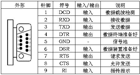
RS-232 is a standard interface with a D-shaped 9-pin connector, and the signal definitions for the connected devices are the same, as defined below:
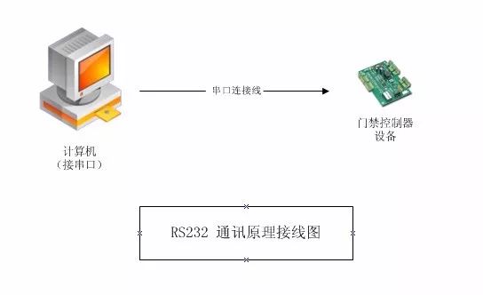
RS-232 only allows point-to-point communication (single-station capability).
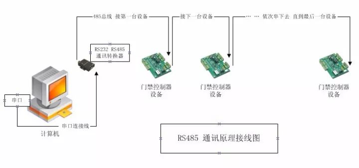
RS-485 allows up to 128 transceivers to be connected on the bus (multi-station capability).
Since PCs are only equipped with RS-232 interfaces by default, there are two ways to obtain RS-485 circuits on the PC:
-
(1)Convert the RS-232 signal from the PC’s serial port to RS-485 using an RS-232/RS-485 conversion circuit. For complex industrial environments, it is best to choose products with surge protection and isolation.
-
(2)Use a PCI multi-serial port card that directly outputs RS-485 type signals.
The computer connects multiple 485 devices (access control controllers) through an RS-232 to RS-485 converter, using a polling method to communicate with the devices on the bus in turn.
The wiring markings are 485+ and 485-, corresponding to the connected devices (controllers) 485+ and 485-.
The communication distance: the theoretical distance from the farthest device (controller) to the computer is 1200 meters, but it is recommended to keep it within 800 meters for better performance, ideally within 300 meters. If the distance is too long, a 485 repeater (extender) can be purchased (please consult a professional converter manufacturer for purchase; the placement of the repeater should be in the middle of the bus or at the beginning, refer to the relevant manufacturer’s manual). The repeater can theoretically extend the distance to 3000 meters.
Load quantity: that is, how many devices (controllers) a single 485 bus can support, which depends on the communication chip of the controller and the communication chip of the 485 converter. Generally, options include 32, 64, 128, and 256 devices. This is a theoretical number; in practical applications, the actual load may not meet the specifications due to environmental factors and communication distance. The Weigang company’s controllers and converters are designed for 256 devices, but it is recommended to keep the number of devices on each bus within 80.
The 485 communication bus (must use twisted pair or one pair of wires from a network cable) should not use ordinary wires (without twisting), as this will cause significant interference, leading to poor communication or even communication failure.
Each controller device must be connected in series; star connections or branches are not allowed. If there are star connections or branches, interference will be significant, leading to poor communication or even communication failure.
This article is sourced from the internet for reference only, with slight modifications by the editor!