What are the differences between serial ports, COM ports, TTL, RS-232, and RS-485? We often encounter these in our projects, so let’s summarize them.
1. Serial ports and COM ports refer to the physical interface form (hardware). TTL, RS-232, and RS-485 refer to the level standards (electrical signals).
2. When connecting devices, generally only GND, RX, and TX are connected. The Vcc or +3.3V power line is usually not connected to avoid conflicts with the power supply of the target device.
3. The PL2303 and CP2102 chips are USB to TTL serial chips that use USB to extend the serial port (TTL level).
4. The MAX232 chip is a dedicated bidirectional conversion chip between TTL level and RS-232 level, capable of converting TTL to RS-232 and vice versa.
5. The TTL standard has a low level of 0 and a high level of 1 (+5V level). The RS-232 standard has a positive level of 0 and a negative level of 1 (±15V level).
6. RS-485 is similar to RS-232 but uses differential signaling with negative logic. This will be skipped for now.
Serial Port and COM Port:
COM port refers to the serial communication port, abbreviated as serial port. This is distinct from USB’s “Universal Serial Bus” and hard disk’s “SATA”.
We usually see two types of physical standards: the D-type 9-pin connector and the 4-pin Dupont connector.
This is a common 4-pin serial port, often found on circuit boards, frequently with Dupont pins on top. Sometimes there is a fifth pin for the +3.3V power supply.
Since it is reserved on the circuit board, the protocol can vary widely, depending on the specific device.
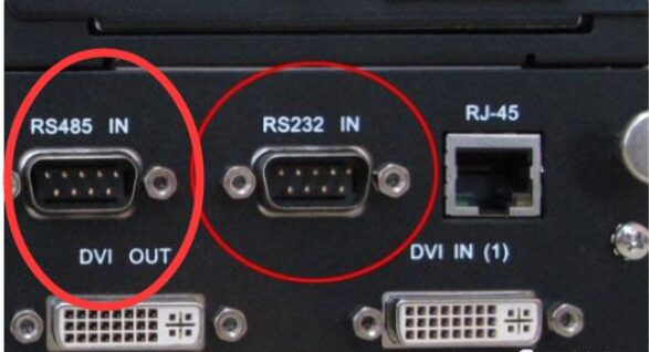
The following image shows the D-type 9-pin serial port (commonly referred to). It can be seen at the back of desktop computers.
Remember, this type of interface only has two protocols: RS-232 and RS-485. It will not be TTL level (unless for special applications).
Generally, we only connect RXD and TXD pins, plus GND.

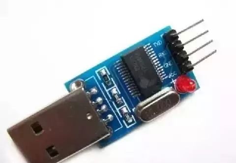
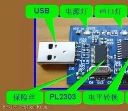
The image below shows a USB to TTL serial board, which can extend a serial port using USB. The chip is PL2303HX.
Various serial ports are often confused online, but this one can indeed be used to download programs to STC microcontrollers.
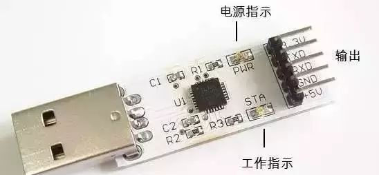
This is another one, with a CP2102 chip, also a USB to TTL serial port. It is said to be better than PL2303, but in practical use, I haven’t felt much difference. This board also has a +3.3V power supply to accommodate different target circuits.
All the above mentioned are USB to TTL serial ports. What if the target device has an RS-232 serial port (D-type 9-pin connector)?
Just connect a MAX232 chip to convert it.
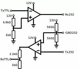
You can also build a simple comparator circuit to achieve the TTL to RS-232 function, as shown in the image below.
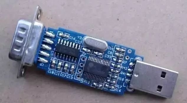
How to convert RS-232 to TTL? You need to think a bit. Of course, someone has already thought of making a product for this. Looking closely at the image, USB is converted to TTL serial through PL2303, and the four holes in the middle can be connected, then converted to RS-232 levels via MAX232, outputting to a 9-pin serial port.
Below is another version: the level conversion still uses the MAX232.
You might buy something like this: it looks like it only has a single chip inside.
But remember, as long as it is a D-type 9-pin serial port, it will not be TTL level. Unless specified otherwise, it is assumed to be RS-232.
Therefore, this cable, regardless of its internal structure, is a USB to RS-232 serial cable.
It is important to emphasize that the serial port of a device can be determined by the output serial cable to be either TTL or RS-232, thus deciding the connection method and whether a conversion circuit is needed.

Weak Current | Communication | Standards | Latest

Recommended Learning:
VIP Technical Exchange Group: Click Me
Weak Current Solutions and Quotes: Click Me
Weak Current Wiring Diagrams Collection: Click Me