Click the blue text above to follow us
Embedded Training – Choose Jufeng Smart Link
Introduction to Ultrasonics
What is ultrasonic?
Ultrasonic waves are sound waves with frequencies higher than the audible range of the human ear (approximately above 20 kHz). In this chapter, we will introduce the HC-SR04, a common ultrasonic sensor module used to measure the distance between an obstacle and the sensor.
When to use ultrasonic?
When to use ultrasonic?
In daily life, ultrasonic waves can be used for distance measurement (such as in car reversing radars), inspecting the internal structure of objects (like ultrasound examinations for fetuses), and even cleaning precision items.
Implementation of Distance Measurement with HC-SR04
Next, we will detail how to implement ultrasonic distance measurement.
Principle of Ultrasonic Distance Measurement
The basic principle of ultrasonic distance measurement is to first emit ultrasonic waves of a certain frequency. When the ultrasonic waves encounter an obstacle, they reflect back. When the module receives the reflected ultrasonic waves, the distance to the obstacle can be calculated by multiplying the time difference between sending and receiving the ultrasonic waves by the speed of sound and dividing by 2.
Formula:
Distance = Time Difference × Speed of Sound ÷ 2
Here, the speed of sound in air is approximately 340 meters/second (depending on temperature and humidity), and the time difference is the total time taken for the ultrasonic wave to travel from emission to reception. Dividing by 2 accounts for the round trip of the ultrasonic wave.
Let’s explain how this time difference is obtained in detail (with code).
(1) When the Trig pin on the HC-SR04 sends a high pulse signal (as shown in the code above), the Echo pin instantly goes high.
(2) During the transmission of the high pulse signal, the Trig remains low, while the Echo stays high.
(3) When the sensor receives the ultrasonic waves reflected from the object, the Echo pin will be pulled low. The duration of the high level on the Echo pin corresponds to the time consumed by the ultrasonic wave during its round trip.
TRIG_Send(1);us_delay(20);TRIG_Send(0);The three lines of code above represent the Trig sending a high pulse signal.
!!! Note: Due to the nature of sound wave propagation, if there is an obstacle closer than the object being measured within the ultrasonic wave’s range, the ultrasonic wave will be reflected prematurely, and the measured distance will be to that obstacle instead. Therefore, when using ultrasonic distance measurement, it is best to have only one object being measured to improve data accuracy.
HC-SR04 Hardware Configuration
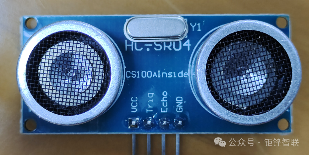
1. Ultrasonic Sensor (HC-SR04)
- Trig Pin: The trigger pin used to send ultrasonic signals.
- Echo Pin: The pin used to receive the reflected ultrasonic signals.
- GND Pin: Ground line
- VCC Pin: Supplies 5V voltage
2. STM32 Microcontroller
- Select any two sets of GPIO pins, one set as the Trig output pin and the other as the Echo input pin.
- Use a timer (such as TIM4) to calculate the time interval.
3. Input Capture Mode
Why use input capture mode?
As mentioned above, we need to calculate the duration of the high level on the Echo pin, so we need to measure the duration of the high level on the Echo pin. It sounds simple, just detect the level change on the Echo pin, right? As soon as we read a high level on the Echo pin, we start the timer; when we read a low level, we read the timer value to get the time difference. However, this approach has a significant drawback: the software loop that continuously reads the GPIO hardware for high/low levels and then reads the timer value takes time, making the data less accurate. Therefore, we need a more precise method – using input capture mode.
In brief, input capture mode records the counter value into the capture register immediately when a rising edge (or falling edge) is detected on the timer input channel, for the program to read later.
For general and advanced timers, each input channel has its own capture register. Input capture can capture the counter value when a rising or falling edge occurs on the input signal. Using another input channel’s capture register for input capture is called indirect mode, while capturing to its own register is called direct mode.
Advanced Timers: STM32’s TIM1, TIM8
General Timers: STM32’s TIM2, TIM3, TIM4, TIM5

Image source: Keysking blogger on Bilibili
Now let’s introduce the overall operation of input capture mode in detail:
As shown in the figure, we use the input capture mode of input channel TI1, with the edge detector set to rising edge. Once the timer starts counting, if a rising edge signal appears on input channel TI1, it enters the input filter (to remove noise and interference from the input signal). The edge detector immediately detects the rising edge, and then a trigger signal passes through TI1FP1, enters the prescaler to process the signal frequency, and is passed to capture register 1. Finally, the capture register detects and assigns the counter value to itself, resetting the counter to 0. This way, we obtain the timer value at the moment the rising edge occurs. However, an edge detector can only be set for either rising or falling edge, not both. Therefore, we need to use another line TI1FP2 on the edge detector, borrowing capture register 2, and set it for falling edge capture to obtain the timer value at the moment the falling edge occurs. By subtracting the two, we can get the duration of the high level.
4. Code Configuration
We will use main.c, main.h, HC_SR04.c, HC_SR04.h, SysTick.h, and SysTick.c. I will not introduce the code configuration for SysTick.h and SysTick.c, but I will attach the relevant code. Just know that this allows us to use delay functions.
HC_SR04.c File
#include "HC_SR04.h"
#include "stm32f10x.h"
#include "SysTick.h"// Header file for delay functions, providing necessary delay functions
extern uint16_t mscount = 0;

void HC_SR04Config(void){
    GPIO_InitTypeDef GPIO_hcsr04init;
    TIM_TimeBaseInitTypeDef TIM_hcsr04init;
    NVIC_InitTypeDef NVIC_hcsr04init;

    RCC_APB2PeriphClockCmd(RCC_APB2Periph_GPIOB, ENABLE);
    RCC_APB1PeriphClockCmd(RCC_APB1Periph_TIM4, ENABLE);

    NVIC_PriorityGroupConfig(NVIC_PriorityGroup_1);

//Trig PB11
    GPIO_hcsr04init.GPIO_Mode = GPIO_Mode_Out_PP;
    GPIO_hcsr04init.GPIO_Pin = GPIO_Pin_11;// Configure GPIOB pin 11 as push-pull output mode, connected to HC-SR04 Trig pin to trigger ultrasonic signal.
    GPIO_hcsr04init.GPIO_Speed = GPIO_Speed_50MHz;
    GPIO_Init(GPIOB,  &GPIO_hcsr04init);

//ECHO PB10
    GPIO_hcsr04init.GPIO_Mode = GPIO_Mode_IN_FLOATING;
    GPIO_hcsr04init.GPIO_Pin = GPIO_Pin_10;// Configure GPIOB pin 10 as floating input mode, connected to HC-SR04 Echo pin to receive reflected ultrasonic signals.
    GPIO_Init(GPIOB,  &GPIO_hcsr04init);

    // Configure Timer TIM4
    TIM_hcsr04init.TIM_ClockDivision = TIM_CKD_DIV1;
    TIM_hcsr04init.TIM_CounterMode   = TIM_CounterMode_Up;
    TIM_hcsr04init.TIM_Period        = 1000-1;// Each count of the timer represents 1 microsecond.
    TIM_hcsr04init.TIM_Prescaler     = 72-1;// Prescaler is 71 (72MHz / 72 = 1MHz)
    TIM_TimeBaseInit(TIM4,&TIM_hcsr04init);// Configure timer overflow interrupt and disable the timer (enable when needed).
    TIM_ITConfig(TIM4,TIM_IT_Update, ENABLE);
    TIM_Cmd(TIM4,DISABLE);

    // Configure NVIC priority and enable TIM4 interrupt for timer overflow.
    NVIC_hcsr04init.NVIC_IRQChannel                   = TIM4_IRQn;
    NVIC_hcsr04init.NVIC_IRQChannelPreemptionPriority = 0;
    NVIC_hcsr04init.NVIC_IRQChannelSubPriority        = 0;
    NVIC_hcsr04init.NVIC_IRQChannelCmd                = ENABLE;
    NVIC_Init(&NVIC_hcsr04init);
}

//Open_tim4() function enables TIM4 timer and resets the counter.
void Open_tim4(void){
  TIM_SetCounter(TIM4,0);
  mscount = 0;// mscount is used to record the number of interrupts.
  TIM_Cmd(TIM4,ENABLE);
}

//Close_tim4() function disables TIM4 timer, stopping the count.
void Close_tim4(void){
  TIM_Cmd(TIM4,DISABLE);
}

// This is the timer overflow interrupt handler. Each time the timer overflows, the value of mscount increases by 1.
void TIM4_IRQHandler(void){
   if( TIM_GetITStatus(TIM4,TIM_IT_Update)!=RESET)   {
      TIM_ClearITPendingBit(TIM4, TIM_IT_Update);
      mscount++;
   }
}

// This function is used to get the return time of the Echo signal, calculate the total time (in microseconds), and reset the timer counter.
int GetEcho_time(void){
  uint32_t t = 0;
  t = mscount*1000;
  t += TIM_GetCounter(TIM4);
  TIM4->CNT = 0;
  ms_delay(50);
  return t;
}

// Get the distance of the ultrasonic wave
float Getlength(void){
int i = 0;
uint32_t t = 0;
float length = 0;
float sum = 0;
while(i != 5)    {
    TRIG_Send(1);
    us_delay(20);
    TRIG_Send(0);
    while(ECHO_Reci == 0);
    Open_tim4();
    i = i+1;
    while(ECHO_Reci == 1);
    Close_tim4();
    t = GetEcho_time();
    length = ((float)t / 58.0);
    sum = sum+length;
}
    length = sum / 5.0;// Take the average distance from the total of five measurements.
    return length;
}
Based on this code, I will provide a detailed introduction.
Code Structure:
1. Enable and disable the timer (TIM4)
Open_tim4():
Enables the TIM4 timer and resets the counter. The timer starts counting to calculate the time interval from signal emission to reception.
Close_tim4(): Closes the TIM4 timer, stopping the count.
2. Timer Overflow Interrupt Handling (TIM4_IRQHandler)
When the timer overflows, mscount increases by 1.
3. Calculate Echo Time (GetEcho_time)
GetEcho_time(): This function returns the total time from when the timer starts counting to the current time. This time is counted from the last timer reset. This function resets the timer counter to ensure the next timing starts from zero.
4. Get the Distance of the Ultrasonic Wave (Getlength)
Getlength(): This function sends a signal and receives the echo signal, calculating the distance based on the round trip time. It measures multiple times (5 times) and takes the average to reduce error.
Difficulties/Confusions
extern uint16_t mscount = 0;
mscount is an external variable updated in
<span>TIM4_IRQHandler</span>, used to count the number of interrupts.The time we obtain is actually represented by t in int GetEcho_time(void){
uint32_t t=0;
t=mscount*1000;
t+=TIM_GetCounter(TIM4);
TIM4->CNT =0;
ms_delay(50);
return t;
}
This code means the total time t = number of interrupts * 1000 + timer time.
The number of interrupts n * 1000 actually represents n/millisecond.
The timer time is the time less than 1 millisecond.
This is the timer overflow interrupt handler. Each time the timer overflows, the value of mscount increases by 1.
void TIM4_IRQHandler(void){
if( TIM_GetITStatus(TIM4,TIM_IT_Update)!=RESET)
{
TIM_ClearITPendingBit(TIM4, TIM_IT_Update);
mscount++;
}
}
if( TIM_GetITStatus(TIM4,TIM_IT_Update)!=RESET) means the timer has overflowed (not zero).
TIM_ClearITPendingBit(TIM4, TIM_IT_Update); clears the interrupt flag.
while(i != 5)
{
TRIG_Send(1);// Trig pin sends high pulse signal
us_delay(20);
TRIG_Send(0);
while(ECHO_Reci == 0);
Open_tim4();
i = i+1;
while(ECHO_Reci == 1);
Close_tim4();
t = GetEcho_time();
length = ((float)t/58.0);
sum = sum+length;
}
length = sum/5.0;// Take the average distance from the total of five measurements.
return length;
while(ECHO_Reci == 0); When Trig sends a high pulse signal, Echo immediately goes high, and when the Echo level is 1, this line of code passes, executing the following code.
while(ECHO_Reci == 1); Echo receives the high pulse signal sent back from Trig, and when Echo has a falling edge (high level 1 becomes low level 0), it will start executing the code below this while statement.
HC_SR04.h File
#include "stm32f10x.h"

void HC_SR04Config(void);
void Open_tim4(void);// Enable TIM4 timer and reset the counter. This is used to start measuring the duration of the Echo signal.
void Close_tim4(void);// Disable TIM4 timer. This is used to end measuring the duration of the Echo signal.
int GetEcho_time(void);// Get the duration of the Echo signal. Calculate the time of the Echo signal by reading the timer counter value and the number of interrupts.
float Getlength(void);// Calculate and return the distance. By triggering measurements multiple times, obtain the time of multiple Echo signals, and take the average to improve measurement accuracy.
void TIM4_IRQHandler(void);// TIM4 timer interrupt handler function, called whenever the timer overflows. Inside the function, clear the interrupt flag and increase the counter variable mscount to record the number of overflows.

#define ECHO_Reci  GPIO_ReadInputDataBit(GPIOB, GPIO_Pin_10)
#define TRIG_Send(a) if(a) \
                                GPIO_SetBits(GPIOB, GPIO_Pin_11); \
                     else \
                                GPIO_ResetBits(GPIOB, GPIO_Pin_11);
Difficulties/Confusions
#define ECHO_Reci GPIO_ReadInputDataBit(GPIOB, GPIO_Pin_10)
Defines a macro
<span>ECHO_Reci</span>to read the input state of GPIOB port pin 10. This macro simplifies the operation of reading the Echo pin status.
#define TRIG_Send(a) if(a) \
GPIO_SetBits(GPIOB, GPIO_Pin_11); \
else
GPIO_ResetBits(GPIOB, GPIO_Pin_11);
Defines a macro
<span>TRIG_Send(a)</span>to set or reset the output state of GPIOB port pin 11. This macro is implemented through an<span>if-else</span>statement:
- If
<span>a</span>is true (non-zero), it calls<span>GPIO_SetBits(GPIOB, GPIO_Pin_11)</span>to set the pin to high level.- Otherwise, it calls
<span>GPIO_ResetBits(GPIOB, GPIO_Pin_11)</span>to set the pin to low level.
Main.c File
#include "stm32f10x.h"
#include "main.h"
#include "HC_SR04.h"
#include "SysTick.h"

void delay(uint16_t time){
uint16_t i = 0;while(time--)    {    i = 12000;while(i--);    }
}

int  main(){
float Length = 0;
HC_SR04Config();
while(1)    {
    Length = Getlength();
printf("%.3f\r\n",Length);// Display with three decimal places and a newline after each output.
ms_delay(500);
}
}
float Length = 0;
Defines a floating-point variable
<span>Length</span>to store the measured distance value. A floating-point type is used because the distance may contain a decimal part, and a floating-point type (<span>float</span>) can store decimal values.int stores integer values.
ms_delay(500);
I used the
<span>ms_delay</span>function here, which is an accurate delay function implemented based on the SysTick timer. I will provide the code below, but I will not explain it; you can view it yourself.
SysTick.c File
#include "SysTick.h"
#include  "stm32f10x.h"

void ms_delay(uint32_t ms){
     uint32_t i;
     SysTick_Config(72000);
     for(i=0;i<ms;i++)  {
          while(!((SysTick->CTRL)&&(1<<16)));
     }
     SysTick->CTRL &&=-SysTick_CTRL_ENABLE_Msk;
}

void us_delay(uint32_t us){
   uint32_t i;
   SysTick_Config(72);
   for(i=0;i<us;i++)  {
          while(!((SysTick->CTRL)&&(1<<16)));
   }
   SysTick->CTRL &&=-SysTick_CTRL_ENABLE_Msk;
}
SysTick.h File
#include  "stm32f10x.h"
void ms_delay(uint32_t ms);
void us_delay(uint32_t us);
I will not show the data display here; you can configure it based on the code above. You can use a serial port or a digital tube to see the distance to the nearest obstacle.

Original link: https://blog.csdn.net/2301_81765286/article/details/147258191