
How to measure the quality of diodes? How to measure the quality of a diode?
Diodes are one of the most commonly used components in electronic circuits, and learning how to measure the quality of a diode is an important skill in the study of electronic circuit knowledge.
Let’s understand how to measure diodes.
1. Methods and Basis for Measuring DiodesThe main tool for measuring diodes is a multimeter, and there are two measurement methods: in-circuit measurement (diode on the circuit board) and out-of-circuit measurement (diode not in the circuit).The basic principle of diode measurement is: based on the basic structure of the diode (mainly the PN junction structure), measure the forward resistance and reverse resistance of the PN junction, and make a basic judgment based on the size of the forward and reverse resistances.To learn how to measure diodes, first, you need to understand the structure and working principle of diodes, and second, you need to understand the main fault characteristics of diodes.
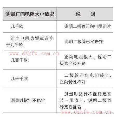
2. Common Fault Characteristics of DiodesThe fault characteristics of common diodes mainly include the following:1. Open Circuit FaultThis fault refers to the disconnection between the positive and negative terminals of the diode, resulting in both forward and reverse resistances becoming infinite. After the diode is open-circuited, the circuit is in an open state.2. Breakdown FaultBreakdown fault refers to the condition where a conductive path has formed between the positive and negative terminals of the diode, with forward and reverse resistances being equal or close (but not infinite).After a diode experiences a breakdown fault, the resistance between the positive and negative terminals may not necessarily be zero, and the behavior of the diode after breakdown varies in different circuits.3. Increased Forward Resistance FaultIf the forward resistance of the diode is too high, the voltage drop across the diode will increase, causing the output signal voltage of the diode to decrease, and the diode may be damaged due to excessive heat. When the forward resistance increases, the unidirectional conductivity of the diode deteriorates.4. Decreased Reverse Resistance FaultIf the reverse resistance of the diode decreases, it will impair the unidirectional conductivity of the diode.5. Deteriorated Performance FaultIn this case, the diode does not exhibit obvious fault phenomena such as open circuit or breakdown, but its performance deteriorates, leading to reduced stability of the circuit operation or decreased output signal voltage.
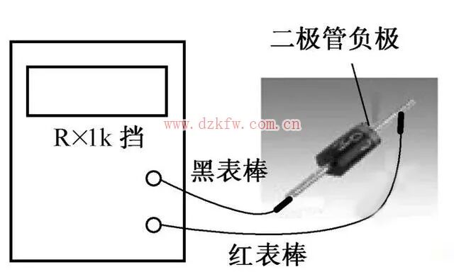
3. Method for Out-of-Circuit Testing of DiodesBelow, we will use an analog multimeter for an example.(Note: The measurements below are based on silicon diodes; if the object being measured is a germanium diode, the values of both reverse and forward resistances will be lower.)1. Measuring Forward ResistanceThe following diagram shows the connection diagram for measuring the forward resistance of a diode using an analog multimeter.
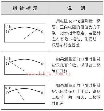
The results of the pointer indication when measuring forward resistance with an analog multimeter are shown in the following diagram.
The situation when measuring forward resistance with an analog multimeter is shown in the following diagram.
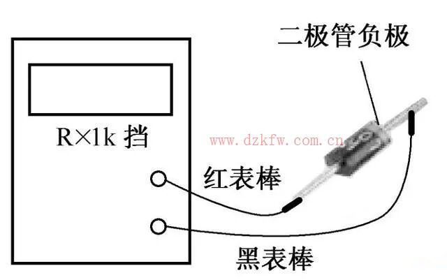
2. Measuring Reverse ResistanceThe following diagram shows the connection diagram for measuring the reverse resistance of a diode using an analog multimeter.
The results of the pointer indication when measuring reverse resistance with an analog multimeter are shown in the following diagram.
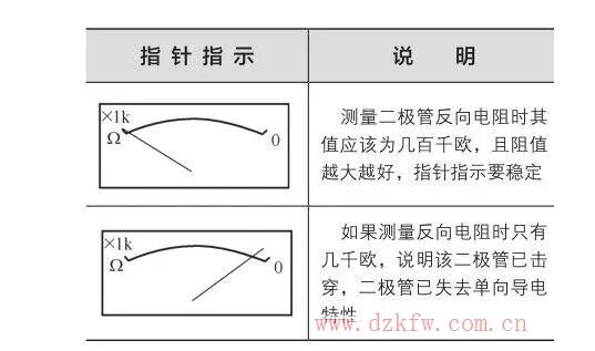
The situation when measuring reverse resistance with an analog multimeter is shown in the following diagram. In-circuit measurement of diodes can be divided into two situations: powered and unpowered; let’s look at each case separately.
4. Method for Unpowered In-Circuit Measurement of DiodesThe following diagram shows the connection diagram for measuring diodes in-circuit while unpowered.The specific method for measuring diodes in-circuit while unpowered and the judgment method for measuring resistance values are basically similar to those when testing diodes individually, but the following points need to be noted:1. The influence of the external circuit on the measurement results is similar to measuring resistors and capacitors in-circuit; the influence of the external circuit on measuring forward resistance is less than that on measuring reverse resistance.2. If there is any doubt about the measurement results, the diode should be removed from the circuit and measured separately.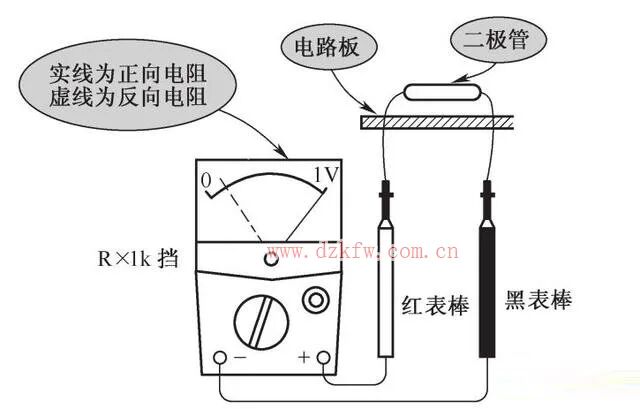 5. Method for Powered In-Circuit Measurement of DiodesIn a powered circuit board, the main measurement is the voltage drop across the diode. A very important characteristic of diodes is that when they are conducting, the voltage drop across them remains basically unchanged. If the voltage drop is normal after conduction, it indicates that the diode is functioning properly.The measurement method is: power the circuit, set the multimeter to the DC voltage 1V range, and the following diagram shows the connection diagram for measuring the voltage drop across the diode in a DC circuit after it is conducting. The red probe connects to the positive terminal of the diode, and the black probe connects to the negative terminal of the diode; the voltage value indicated by the pointer is the forward voltage drop of the diode.
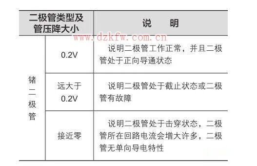
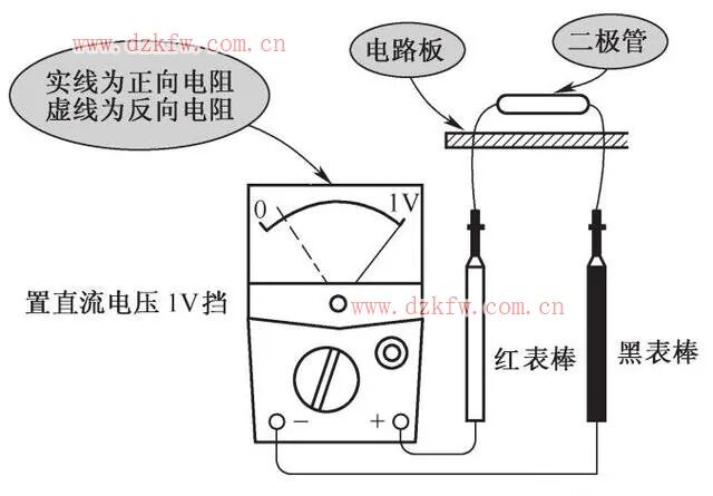 The analysis of the measurement results of the forward voltage drop across the diode is shown in the following diagram.
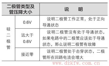
 During the measurement process of the diode, the following points need to be noted:1. In AC circuits, diodes are in a cutoff state under reverse conditions, and the reverse voltage across them is relatively high. The multimeter measures the average voltage across the diode in DC mode, which will be negative voltage at this time.2. The forward and reverse resistances measured for the same diode using different ranges of the same multimeter will differ. The forward and reverse resistances measured for the same diode using different models of multimeters will also differ.3. When measuring the forward resistance of a diode, if the pointer does not quickly stabilize at a certain resistance value but keeps oscillating, it indicates that the thermal stability of the diode is poor.You can directly use the diode function of the multimeter to measure the quality of the diode. Most digital multimeters have this function. When this function is activated, short-circuiting the red and black probes will cause the multimeter buzzer to sound. This function can also be used to verify if there is a disconnection in the circuit. However, when measuring the diode with this function, the buzzer will not sound, and the forward voltage drop of the diode will be displayed on the multimeter screen.Since diodes have positive and negative terminals, the shaded end is the negative terminal. This shaded part can be easily seen on the diode, and when measuring, be careful not to reverse the positive and negative connections. The red probe should connect to the positive terminal of the diode, and the black probe should connect to the negative terminal.
 If the diode is functioning normally, the forward voltage drop will be displayed on the screen, typically around 0.7V for silicon diodes and around 0.3V for germanium diodes. If this occurs, it indicates that the diode is normal; if no result is displayed, the diode is damaged.


Screenshots of electronic books in the resource collection

[Complete Set of Hardware Learning Materials Collection]