For a single-phase motor, connect one probe to ground and measure the resistance of the motor’s starting, running, and common windings. The resistance should be infinite or close to infinite. If there is no resistance or the resistance is very low, it indicates that the motor is faulty. Then measure the resistance of the three windings separately; the starting winding resistance should equal the sum of the running and common winding resistances. The measurement method for three-phase motors is the same as for single-phase motors, except that the resistances of the three windings should be equal. The multimeter measurement: 1. The phase-to-phase resistance should be uniform; it doesn’t matter how large the resistance is, it just needs to be uniform. For motors larger than 15KW, you may measure 0 ohms regardless of how you measure it, which is due to the multimeter’s range being too large. You should use a micro-ohmmeter instead. 2. The insulation resistance between the phase line and the motor casing should be greater than 1M ohm. How to determine the condition of a three-phase asynchronous motor? When measuring a single-phase motor, the capacitor should be disconnected. 1) Use the multimeter to measure the current; the three-phase imbalance rate should not exceed 10%; 2) Use an insulation resistance tester, ensuring each phase to ground and phase-to-phase measurements are not less than 0.5 megaohms; 3) Use a bridge to measure the DC resistance, ensuring the three-phase imbalance rate is not more than 2%. In addition to the above methods, checking whether the windings are normal can be done by connecting a small current range (for example, 50 microamperes) to any two leads with a multimeter. Then rotate the motor; the multimeter needle should swing visibly (depending on the speed of rotation). This method uses the residual magnetism of the motor to check the windings. If the windings are burned out, the needle will definitely not move. A multimeter can determine phase-to-phase short circuits, grounding, and open circuits, but it is not effective for inter-turn short circuits. Relying solely on a multimeter for measurements is not very accurate; it is best to use a megohmmeter to measure the insulation resistance of each phase, then use a DC bridge to measure the DC resistance between the three-phase windings to check for balance, whether the values are too high or too low, for absolute accuracy. The resistances of the three-phase windings should be equal, and the insulation resistance between phases and between phases and the casing should be greater than 1 megaohm. Overloaded windings will burn out, and if one phase is missing, another group will burn out while the other does not.
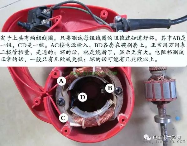 How to Use a Multimeter to Determine the Condition of a Single-Phase Motor? Generally, the DC resistance of the starting winding of a single-phase motor is greater than that of the running winding. The simplest way to determine this is: 1) First, use a multimeter to measure the DC resistance from the common terminal to the running winding terminal and the starting winding terminal. 2) Then, measure the DC resistance from the running winding terminal to the starting winding terminal with the multimeter. 3) If the sum of the two measurements in “1” is not equal to the measurement in “2”, then the motor is definitely burned out! If they are equal, it is best to compare with a motor of the same model or find the factory parameters of the motor for comparison to determine its condition. When measuring a single-phase motor, the capacitor should be disconnected. Short circuits in single-phase motors require a reference resistance value under normal conditions. How to Use a Multimeter to Determine if a Fan Motor is Burned Out? The method is as follows: The fan motor has 5 wires: 1st gear, 2nd gear, 3rd gear, and 2 capacitor wires. Generally, except for a few motors, the three gear wires are red, blue, and green, with the capacitor wires being black and yellow. Now, start by disconnecting all 5 wires from the motor. First, set the multimeter to the ohm range, connect the red probe to any capacitor wire, and the black probe to the 1st gear. Record the resistance value, then measure the 2nd and 3rd gears. Normally, the resistance value should increase with the gear: for example, 1st gear is 70 ohms, 2nd gear is 110 ohms, and 3rd gear is 150 ohms. You can record these values for comparison. In other words, if you measure an infinite resistance for all three gears, or if one gear shows infinite resistance, it indicates that the coil of the motor is burned out or that the coil of one gear is broken. Lastly, measure the 5 wires against the motor casing to check for any short circuits.
To learn more about using a multimeter to check the condition of a three-phase motor, please click on “Read the Original”