How to Choose Between Siemens PLC, Mitsubishi PLC, or Other PLCs? The Most Comprehensive PLC Selection Summary
When designing a PLC system, the first step is to determine the system plan, followed by the design and selection of the PLC. Choosing a PLC mainly involves determining the manufacturer and the specific model of the PLC. If the system plan requires a distributed system or a remote I/O system, network communication requirements must also be considered. So how should one choose a PLC?
1. PLC Manufacturer
Determining the PLC manufacturer should primarily consider the user’s requirements, the designer’s familiarity with different manufacturers’ PLCs, design habits, consistency with supporting products, and technical service factors. From the perspective of the reliability of the PLC itself, as a principle, products from large foreign companies should not have reliability issues.

Generally speaking, for applications controlling independent devices or simpler control systems, using Japanese PLC products tends to offer a certain cost-performance advantage. For larger systems with high network communication requirements and open distributed control systems or remote I/O systems, PLCs produced in Europe and America have advantages in network communication functions. Additionally, for certain specific industries (e.g., metallurgy, tobacco, etc.), one should choose PLC systems that have proven performance and are mature and reliable in the relevant industry field.
2. Input/Output (I/O) Points
The number of PLC input/output points is one of the basic parameters of the PLC. The determination of I/O points should be based on the total number of I/O points required by the controlled devices. In general, the PLC’s I/O points should have an appropriate margin. Usually, after estimating the input and output points, an additional 10% to 20% of expandable margin is added to estimate the number of I/O points. When ordering, adjustments should also be made based on the manufacturer’s PLC product characteristics.
3. Storage Capacity
The memory capacity is the size of the hardware storage units that the programmable controller can provide, while the program capacity is the size of the storage units used by user applications in the memory; thus, the program capacity is less than the memory capacity. During the design phase, since the user application program has not yet been compiled, the program capacity is unknown and will only be known after program debugging. To estimate the program capacity during the design selection, the memory capacity is typically used as a substitute. There is no fixed formula for estimating the PLC memory capacity; many documents provide different formulas, generally based on 10 to 15 times the number of digital I/O points, plus 100 times the number of analog I/O points, and this number is used as the total number of memory words (16 bits per word), with an additional 25% considered for margin.
4. Control Functions
The selection includes choices for operational functions, control functions, communication functions, programming functions, diagnostic functions, and processing speed.
(1) Operational Functions
Simple PLC operational functions include logical operations, timing, and counting functions; ordinary PLCs also include data shifting and comparison operations; more complex operational functions include algebraic operations, data transfer, etc.; large PLCs also include analog PID calculations and other advanced operational functions. With the emergence of open systems, PLCs now generally have communication functions; some products communicate with lower-level devices, while others communicate with peer or upper-level devices, and some even have data communication capabilities with factory or enterprise networks. When selecting, one should base the choice of required operational functions on actual application requirements. Most applications only require logical operations and timing/counting functions; some applications require data transfer and comparison, while others use algebraic operations, numerical conversions, and PID calculations for analog detection and control. When displaying data, decoding and encoding operations may also be needed.
(2) Control Functions
Control functions include PID control calculations, feedforward compensation control calculations, ratio control calculations, etc., and should be determined based on control requirements. PLCs are mainly used for sequential logic control; therefore, in most cases, single-loop or multi-loop controllers are commonly used to solve analog control issues. Sometimes, dedicated intelligent input/output units are used to complete the required control functions, improve PLC processing speed, and save memory capacity. For example, using PID control units, high-speed counters, analog units with speed compensation, ASCII code conversion units, etc.
(3) Communication Functions
Medium and large PLC systems should support multiple field buses and standard communication protocols (such as TCP/IP) and should be able to connect to the factory management network (TCP/IP) when necessary. Communication protocols should comply with ISO/IEEE communication standards and should be open communication networks.
The communication interfaces of the PLC system should include serial and parallel communication interfaces (RS232C/422A/423/485), RIO communication ports, industrial Ethernet, common DCS interfaces, etc.; the communication bus (including interface devices and cables) of medium and large PLCs should be configured with 1:1 redundancy, and the communication bus should meet international standards, with communication distances meeting actual device requirements.
In the communication network of the PLC system, the upper-level network communication speed should exceed 1 Mbps, and the communication load should not exceed 60%. The main forms of the PLC communication network include:
1) A PC as the master station, with multiple PLCs of the same model as slave stations, forming a simple PLC network;
2) One PLC as the master station, with other PLCs of the same model as slave stations, forming a master-slave PLC network;
3) The PLC network is connected to a large DCS through a specific network interface as a subnet of the DCS;
4) A dedicated PLC network (a proprietary communication network from various manufacturers).
To reduce the CPU communication tasks, communication processors with different communication functions (such as point-to-point, field bus, industrial Ethernet) should be chosen according to the actual needs of the network composition.
(4) Programming Functions
Offline programming mode: The PLC and programmer share a CPU; when the programmer is in programming mode, the CPU only serves the programmer and does not control field devices. After programming is completed, the programmer switches to run mode, and the CPU controls the field devices, but cannot be programmed. The offline programming mode can reduce system costs but is inconvenient for use and debugging.
Online programming mode: The CPU and programmer have their own CPUs; the main CPU is responsible for field control and exchanges data with the programmer within a single scanning cycle. The programmer sends the online compiled program or data to the main unit, which runs according to the newly received program in the next scanning cycle. This method has a higher cost but is convenient for system debugging and operation, and is commonly used in medium and large PLCs.
Five standardized programming languages: Sequential Function Chart (SFC), Ladder Diagram (LD), Function Block Diagram (FBD) as graphical languages, and Instruction List (IL), Structured Text (ST) as textual languages. The selected programming language should comply with its standard (IEC6113123) and also support various programming forms such as C, Basic, Pascal, etc., to meet the control requirements of special control situations.
(5) Diagnostic Functions
The diagnostic functions of a PLC include hardware and software diagnostics. Hardware diagnostics determine the fault location through logical judgments of the hardware, while software diagnostics are divided into internal and external diagnostics. Internal diagnostics assess the performance and function of the PLC itself through software, while external diagnostics evaluate the information exchange functions between the PLC’s CPU and external input/output components.
The strength of the PLC’s diagnostic functions directly affects the technical capabilities required from operators and maintenance personnel, and impacts average repair times.
(6) Processing Speed
PLCs operate in a scanning mode. From a real-time requirement perspective, the faster the processing speed, the better. If the signal duration is less than the scanning time, the PLC will miss the signal, resulting in data loss.
Processing speed is related to the length of the user program, CPU processing speed, software quality, etc. Currently, PLC points respond quickly, with a speed of about 0.2 to 0.4 μs per binary instruction execution, thus meeting high control requirements and rapid response needs. The scanning cycle (processor scanning cycle) should meet the following: small PLCs should have a scanning time not exceeding 0.5 ms/K; medium and large PLCs should have a scanning time not exceeding 0.2 ms/K.
5. PLC Models
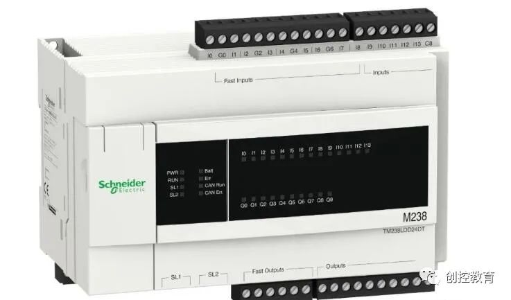
PLC types: PLCs are divided into two categories based on structure: integrated and modular.
Integrated PLCs have fewer and relatively fixed I/O points, thus offering less flexibility for user selection, and are usually used in small control systems. Representative models of this type include Siemens’ S7-200 series, Mitsubishi’s FX series, and Omron’s CPM1A series.
Modular PLCs provide various I/O modules that can be plugged onto the PLC baseboard, allowing users to reasonably select and configure the number of I/O points for the control system as needed. Therefore, modular PLCs offer more flexible configurations and are generally used in medium and large control systems, such as Siemens’ S7-300 and S7-400 series, Mitsubishi’s Q series, and Omron’s CVM1 series.
6. Selection of Various Modules
(1) Digital I/O Modules
The selection of digital input/output modules should consider application requirements. For input modules, factors such as input signal levels and transmission distances must be taken into account. Output modules also come in various types, such as relay contact output types, AC120V/230V bidirectional thyristor output types, DC24V transistor-driven types, and DC48V transistor-driven types.
Generally, relay output modules have advantages of low cost and a wide voltage range but have a shorter lifespan and longer response times, requiring surge absorption circuits when used with inductive loads; bidirectional thyristor output modules have faster response times suitable for frequent switching and low-power factor inductive loads, but are more expensive and have poorer overload capabilities.
Additionally, input/output modules can be categorized by the number of input/output points: 8 points, 16 points, 32 points, etc. The selection should be based on actual needs.
(2) Analog I/O Modules
Analog input modules can be divided according to the type of input signal: current input, voltage input, thermocouple input, etc. The typical signal levels for current inputs are 4-20 mA or 0-20 mA; voltage input modules typically have signal levels of 0-10V, -5V to +5V, etc. Some analog input modules can be compatible with either voltage or current input signals.
Analog output modules are similarly divided into voltage output modules and current output modules, with current output signals typically being 0-20 mA or 4-20 mA. Voltage output signals usually range from 0-10V, -10V to +10V, etc. Analog input/output modules can be categorized by the number of input/output channels: 2 channels, 4 channels, 8 channels, etc.
(3) Function Modules
Function modules include communication modules, positioning modules, pulse output modules, high-speed counting modules, PID control modules, temperature control modules, etc. When selecting PLCs, the compatibility of function modules should be considered, and the selection of function modules involves both hardware and software aspects.
In terms of hardware, the functionality of the modules should be easily connectable to the PLC, and the PLC should have relevant connections, installation locations, interfaces, and connection cables as accessories. In terms of software, the PLC should have corresponding control functions and should be easy to program for the function modules. For example, Mitsubishi’s FX series PLC can conveniently control corresponding function modules using the “FROM” and “TO” instructions.
7. Redundancy Functions
(1) Control Unit Redundancy
1. Important process units: CPU (including memory) and power supply should be 1B1 redundant.
2. When necessary, a hot standby redundancy system composed of PLC hardware and hot standby software, or dual or triple redundancy fault-tolerant systems can also be selected.
(2) I/O Interface Unit Redundancy 1. Multi-point I/O cards for control loops should be configured with redundancy.
2. Multi-point I/O cards for important detection points can be configured with redundancy. 3) For important I/O signals, dual or triple I/O interface units can be selected.
General Principles
Once the PLC model and specifications are generally determined, the basic specifications and parameters of each component of the PLC can be determined one by one based on control requirements, and the model of each component module can be selected. When selecting module models, the following principles should be followed.
(1) Economy
When selecting a PLC, consideration should be given to the performance-to-price ratio. When considering economy, factors such as the scalability, operability, and return on investment of the application should also be compared and balanced to ultimately select a satisfactory product.
The number of input/output points directly affects the price. Each additional input/output card incurs additional costs. When the number of points increases to a certain value, corresponding memory capacity, rack, motherboard, etc., must also increase, thus affecting the selection of CPU, memory capacity, and control function range. Sufficient consideration should be given during estimation and selection to ensure a reasonable performance-to-price ratio for the entire control system.
(2) Convenience
Generally speaking, as PLCs, there are often many types of modules that can meet control requirements. The selection should prioritize simplifying circuit design, ease of use, and minimizing external control devices. For example, for input modules, priority should be given to those that can connect directly with external detection elements, avoiding the use of interface circuits. For output modules, priority should be given to those capable of directly driving loads, minimizing intermediate relay components.
(3) Universality
When selecting, consideration should be given to the unification and universality of the PLC’s components to avoid having too many types of modules. This not only facilitates procurement and reduces spare parts but also increases the interchangeability of the various components in the system, providing convenience for design, debugging, and maintenance.
(4) Compatibility
When selecting the components of the PLC system, sufficient consideration should be given to compatibility. To avoid compatibility issues, the number of manufacturers for the main components of the PLC system should not be excessive. If possible, products from the same manufacturer should be prioritized.
(Content source from the internet, copyright belongs to the original author)Disclaimer: If there are copyright issues, please contact for deletion!No individual or organization assumes relevant legal responsibility.