
1. Bit Logic Instructions
1.1 -||- Normally Open Contact (Address) 1.2 -|/|- Normally Closed Contact (Address) 1.3 XOR Bitwise Exclusive OR 1.4 -|NOT|- Signal Flow Inversion 1.5 -( ) Output Coil 1.6 -(#)- Intermediate Output 1.7 -(R) Coil Reset 1.8 -(S) Coil Set 1.9 RS Reset-Set (Set-Reset) Trigger 1.10 -(N)- RLO Falling Edge Detection 1.11 -(P)- PLO Rising Edge Detection 1.12 -(SAVE) Save RLO to BR Memory 1.13 MEG Address Falling Edge Detection 1.14 POS Address Rising Edge Detection
2. Comparison Instructions
2.1 CMP?I Integer Comparison 2.2 CMP?D Double Integer Comparison 2.3 CMP?R Real Number Comparison
3. Conversion Instructions
3.1 BCD_IB Convert BCD Code to Integer 3.2 I_BCD Convert Integer to BCD Code 3.3 I_DINT Convert Integer to Double Integer 3.4 BCD_DI Convert BCD Code to Double Integer 3.5 DI_BCD Convert Double Integer to BCD Code 3.6 DI_REAL Convert Double Integer to Floating Point 3.7 INV_I Integer’s Binary Inversion 3.8 INV_DI Double Integer’s Binary Inversion 3.9 NEG_I Integer’s Binary Complement 3.10 NEG_DI Double Integer’s Binary Complement 3.11 NEG_R Floating Point Negation 3.12 ROUND Round to Double Integer 3.13 TRUNC Truncate Decimal to Double Integer 3.14 CEIL Round Up 3.15 FLOOR Round Down
4. Counter Instructions
4.1 S_CUD Increment/Decrement Counter 4.2 S_CU Increment Counter 4.3 S_CD Decrement Counter 4.4 -(SC) Set Initial Value for Counter 4.5 -(CU) Increment Counter Coil 4.6 -(CD) Decrement Counter Coil
5. Data Block Instructions
5.1 -(OPN) Open Data Block: DB or DI
6. Logic Control Instructions 6.1 -(JMP) Unconditional Jump 6.2 -(JMP) Conditional Jump 6.3 -(JMPN) Jump if Not 6.4 LABEL Label
7. Integer Arithmetic Operation Instructions
7.1 ADD_I Integer Addition 7.2 SUB_I Integer Subtraction 7.3 MUL_I Integer Multiplication 7.4 DIV_I Integer Division 7.5 ADD_DI Double Integer Addition 7.6 SUB_DI Double Integer Subtraction 7.7 MUL_DI Double Integer Multiplication 7.8 DIV_DI Double Integer Division 7.9 MOD_DI Modulus of Double Integer
8. Floating Point Arithmetic Operation Instructions
8.1 Basic Instructions 8.1.1 ADD_R Real Addition 8.1.2 SUB_R Real Subtraction 8.1.3 MUL_R Real Multiplication 8.1.4 DIV_R Real Division 8.1.5 ABS Floating Point Absolute Value Operation
8.2 Extended Instructions
8.2.1 SQR Floating Point Square 8.2.2 SQRT Floating Point Square Root 8.2.3 EXP Floating Point Exponential Operation 8.2.4 LN Floating Point Natural Logarithm Operation 8.2.5 SIN Floating Point Sine Operation 8.2.6 COS Floating Point Cosine Operation 8.2.7 TAN Floating Point Tangent Operation 8.2.8 ASIN Floating Point Arcsine Operation 8.2.9 ACOS Floating Point Arccosine Operation 8.2.10 ATAN Floating Point Arctangent Operation
9. Assignment Instructions
9.1 MOVE Assignment
10. Program Control Instructions
10.1 -(Call) Call FC/SFC from Coil (No Parameters) 10.2 CALL_FB Call FB from Block 10.3 CALL_FC Call FC from Block 10.4 CALL_SFB Call SFB from Block 10.5 CALL_SFC Call SFC from Block 10.6 -(MCR<) Enable Master Control Relay 10.7 -(MCR>) Disable Master Control Relay 10.8 -(MCRA) Start Master Control Relay 10.9 -(MCRD) Stop Master Control Relay 10.10 -(RET) Return
11. Shift and Loop Instructions
11.1 Shift Instructions 11.1.1 SHR_I Integer Right Shift 11.1.2 SHR_DI Double Integer Right Shift 11.1.3 SHL_W Word Left Shift 11.1.4 SHR_W Word Right Shift 11.1.5 SHL_DW Double Word Left Shift 11.1.6 SHR_DW Double Word Right Shift
11.2 Loop Instructions
11.2.1 ROL_DW Double Word Left Rotate 11.2.2 ROR_DW Double Word Right Rotate
12. Status Bit Instructions
12.1 OV -||- Overflow Exception Bit 12.2 OS -||- Storage Overflow Exception Bit 12.3 UO -||- Unordered Exception Bit 12.4 BR -||- Exception Bit Binary Result 12.5 ==0-||- Result Bit Equals “0” 12.6 <>0-||- Result Bit Not Equal “0” 12.7 >0-||- Result Bit Greater Than “0” 12.8 <0-||- Result Bit Less Than “0” 12.9 >=0-||- Result Bit Greater Than or Equal to “0” 12.10 <=0-||- Result Bit Less Than or Equal to “0”
13. Timer Instructions
13.1 S_PULSE Pulse S5 Timer 13.2 S_PEXT Extended Pulse S5 Timer 13.3 S_ODT On Delay S5 Timer 13.4 S_ODTS Retentive On Delay S5 Timer 13.5 S_OFFDT Off Delay S5 Timer 13.6 -(SP) Pulse Timer Coil 13.7 -(SE) Extended Pulse Timer Coil 13.8 -(SD) On Delay Timer Coil 13.9 -(SS) Retentive On Delay Timer Coil 13.10 -(SF) Off Delay Timer Coil
14. Word Logic Instructions
14.1 WAND_W Word AND Operation 14.2 WOR_W Word OR Operation 14.3 WAND_DW Double Word AND Operation 14.4 WOR_DW Double Word OR Operation 14.5 WXOR_W Word XOR Operation 14.6 WXOR_DW Double Word XOR Operation
Basic Logic Instructions for Mitsubishi FX Series PLC
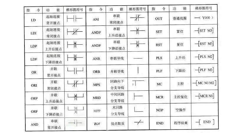
Input and Output Instructions (LD/LDI/LDP/LDF/OUT)
(1) LD (Input Instruction) A normally open contact connected to the left bus, each logical line starting with a normally open contact uses this instruction.
(2) LDI (Inverted Input Instruction) A normally closed contact connected to the left bus, each logical line starting with a normally closed contact uses this instruction.
(3) LDP (Rising Edge Input Instruction) A normally open contact connected to the left bus for rising edge detection, only activated for one scan cycle when the specified bit element rises (from OFF to ON).
(4) LDF (Falling Edge Input Instruction) A normally closed contact connected to the left bus for falling edge detection.
(5) OUT (Output Instruction) An instruction to drive the coil, also known as the output instruction.
Usage Instructions for Input and Output Instructions:
1) LD and LDI instructions can be used for contacts connected to the left bus, and can also be used in conjunction with ANB and ORB instructions to achieve block logic operations;
2) LDP and LDF instructions only maintain activation for one scan cycle when the corresponding element is valid.
3) The target elements for LD, LDI, LDP, and LDF instructions are X, Y, M, T, C, S; 4) The OUT instruction can be used multiple times (equivalent to parallel coils), for timers and counters, a constant K or data register should be set after the OUT instruction.
5) The target elements for OUT instructions are Y, M, T, C, and S, but cannot be used for X.
Series Contact Instructions (AND/ANI/ANDP/ANDF)
(1) AND (AND Instruction) A normally open contact series connection instruction, completing a logical “AND” operation.
(2) ANI (AND NOT Instruction) A normally closed contact series connection instruction, completing a logical “NAND” operation.
(3) ANDP Rising edge detection series connection instruction.
(4) ANDF Falling edge detection series connection instruction.
Usage Instructions for Series Contact Instructions:
1) AND, ANI, ANDP, ANDF are instructions for single contact series connections, with no limit on the number of series connections, can be reused.
2) The target elements for AND, ANI, ANDP, ANDF are X, Y, M, T, C, and S.
3) The OUT M101 instruction then drives Y4 through the T1 contact, known as continuous output.
Parallel Contact Instructions (OR/ORI/ORP/ORF)
(1) OR (OR Instruction) Used for a single normally open contact in parallel, achieving a logical “OR” operation.
(2) ORI (OR NOT Instruction) Used for a single normally closed contact in parallel, achieving a logical “NOR” operation.
(3) ORP Rising edge detection parallel connection instruction.
(4) ORF Falling edge detection parallel connection instruction.
Usage Instructions for Parallel Contact Instructions:
1) OR, ORI, ORP, ORF instructions refer to the parallel connection of single contacts, with the left end connected to LD, LDI, LDP or LDF, and the right end connected to the right end of the corresponding contact of the previous instruction. The number of consecutive uses of parallel contact instructions is unlimited;
2) The target elements for OR, ORI, ORP, ORF instructions are X, Y, M, T, C, S.
Block Operation Instructions (ORB / ANB)
(1) ORB (Block OR Instruction) Used for parallel connection between two or more series connected circuits.
Usage Instructions for ORB Instruction:
1) When several series circuit blocks are connected in parallel, each series circuit block should start with LD or LDI instructions;
2) If there are multiple circuit blocks in parallel, using ORB instruction for each circuit block allows unlimited numbers of parallel circuit blocks;
3) ORB instruction can also be used consecutively, but this programming style is not recommended, and the usage of LD or LDI instructions should not exceed 8 times, meaning ORB can only be used less than 8 times continuously.
(2) ANB (Block AND Instruction) Used for series connection between two or more parallel connected circuits.
Usage Instructions for ANB Instruction:
1) When connecting parallel circuit blocks in series, the start of each parallel circuit block should use LD or LDI instructions;
2) When connecting multiple parallel loop blocks in series to the previous loop, there is no limit on the number of uses of ANB instructions. ANB can also be used consecutively, but like ORB, the number of uses should be below 8.
Set and Reset Instructions (SET/RST)
(1) SET (Set Instruction) Its function is to set the target element and maintain it.
(2) RST (Reset Instruction) Resets the target element and maintains it in the zero state. The use of SET and RST instructions allows Y0 to turn ON and remain ON even if X0 is disconnected; only when X1 is activated does Y0 turn OFF and remain OFF.
Usage Instructions for SET and RST Instructions:
1) The target elements for SET instructions are Y, M, S, and for RST instructions are Y, M, S, T, C, D, V, Z. The RST instruction is often used to clear the contents of D, Z, V, and to reset accumulated timers and counters.
2) For the same target element, SET and RST can be used multiple times, and the order can be arbitrary, but the last executor is valid.
Differential Instructions (PLS/PLF)
(1) PLS (Rising Edge Differential Instruction) Generates a pulse output for one scan cycle on the rising edge of the input signal;
(2) PLF (Falling Edge Differential Instruction) Generates a pulse output for one scan cycle on the falling edge of the input signal.
Using differential instructions to detect signal edges, controlling the state of Y0 through set and reset commands.
Usage Instructions for PLS and PLF Instructions:
1) The target elements for PLS and PLF instructions are Y and M;
2) When using PLS, the target element is ON only during one scan cycle after the input is ON, M0 is ON only during one scan cycle when the normally open contact of X0 changes from OFF to ON; when using PLF, it only drives the input signal’s falling edge, with everything else the same as PLS.
Master Control Instructions (MC/MCR)
1) MC (Master Control Instruction) Used for connecting common series contacts. After executing MC, the left bus moves behind the MC contact.
2) MCR (Master Control Reset Instruction) It is the reset instruction for the MC instruction, restoring the original position of the left bus using the MCR instruction.
When programming, it is common to have multiple coils controlled by one or a group of contacts; if the same contacts are inserted into each coil’s control circuit, it will occupy many storage units. Using master control instructions can solve this problem.
MC, MCR instructions can use MC N0 M100 to shift the left bus right, making Y0 and Y1 under the control of X0, where N0 indicates the nesting level, and in non-nested structures, the usage of N0 is unlimited; using MCR N0 restores to the original left bus state. If X0 disconnects, it will skip the instructions between MC and MCR and execute downward.
Usage Instructions for MC and MCR Instructions:
1) The target elements for MC and MCR instructions are Y and M, but cannot use special auxiliary relays. MC occupies 3 program steps, and MCR occupies 2 program steps;
2) Master control contacts in ladder diagrams are vertical to general contacts. Master control contacts are normally open contacts connected to the left bus, acting as the main switch for controlling a group of circuits. Contacts connected to master control contacts must use LD or LDI instructions.
3) When the input contact of the MC instruction disconnects, the accumulated timers, counters, and elements driven by reset/set instructions within MC and MCR maintain their previous states. Non-accumulated timers and counters, elements driven by OUT instructions will reset, meaning when X0 disconnects, Y0 and Y1 will become OFF.
4) If another MC instruction is used within an MC instruction area, it is called nesting. The maximum nesting level is 8, numbered in increasing order from N0 to N7, with each level returning using the corresponding MCR instruction, starting from the highest numbered nesting level.
Stack Instructions (MPS/MRD/MPP)
Stack instructions are new basic instructions in the FX series, used for multiple output circuits, providing convenience for programming. The FX series PLC has 11 storage units specifically used to store intermediate results of program calculations, referred to as stack memory.
(1) MPS (Push Instruction) Sends the calculation result into the first segment of stack memory, while moving previously sent data to the next segment of the stack.
(2) MRD (Read Stack Instruction) Reads the first segment of data from stack memory (the last data pushed onto the stack) and continues to retain that data in the first segment of stack memory, without moving the data within the stack.
(3) MPP (Pop Instruction) Reads the first segment of data from stack memory (the last data pushed onto the stack) and that data disappears from the stack, while other data within the stack moves up sequentially.
Usage Instructions for Stack Instructions:
1) Stack instructions have no target elements;
2) MPS and MPP must be used in pairs;
3) Since there are only 11 stack memory units, the stack can have a maximum of 11 levels.
Logical Inversion, No Operation, and End Instructions (INV/NOP/END)
1) INV (Inversion Instruction) After executing this instruction, the original calculation result is inverted. The usage of the inversion instruction is shown in the diagram; if X0 disconnects, Y0 is ON, otherwise, Y0 is OFF. Note that INV cannot be connected to the bus like LD, LDI, LDP, LDF instructions, nor can it be used independently like OR, ORI, ORP, ORF instructions.
2) NOP (No Operation Instruction) Performs no operation but occupies one program step. When executing NOP, nothing is done; sometimes NOP instructions can be used to short-circuit certain contacts or to overwrite unwanted instructions. When the PLC performs a clear operation on the user memory, the contents of the user memory become all no-operation instructions.
3) END (End Instruction) Indicates the end of the program. If the END instruction is not written at the end of the program, the PLC will execute from the first step of the user program memory to the last step regardless of how long the actual user program is; if there is an END instruction, when scanned to END, the program execution ends, thus shortening the scan cycle. During program debugging, several END instructions can be inserted to divide the program into several segments, and after confirming that the previous program segment is correct, the END instructions can be deleted one by one until debugging is complete.
Step Instructions for FX Series PLC
1. Step Instructions (STL/RET)
Step instructions are designed specifically for sequential control. Many control processes in industrial control can be implemented using sequential control, and using step instructions for sequential control is both convenient for implementation and easy to read and modify.
In FX2N, there are two step instructions: STL (Step Contact Instruction) and RET (Step Return Instruction).
STL and RET instructions only have stepping functionality when used with state devices S. For example, STL S200 represents a state normally open contact, referred to as STL contact, which is symbolized as -|| ||- in ladder diagrams, and it has no normally closed contacts. Each state device S records a step, e.g., when STL S200 is valid (ON), it enters the step represented by S200 (similar to the main switch for this step), beginning to execute the work that should be done at this stage and determining whether the conditions for entering the next step are met. Once the end of this step signal is ON, S200 is turned off to enter the next step, such as S201 step. RET instruction is used to reset the STL instruction. After executing RET, it returns to the bus, exiting the stepping state.
2. State Transition Diagram
A sequential control process can be divided into several stages, also called steps or states, each with different actions. When the transition conditions between adjacent states are met, the transition is realized, i.e., from the previous state to the next state execution. We often use state transition diagrams (function table diagrams) to describe this sequential control process. Each state is recorded by state devices S, and X is the transition condition. For example, when X1 is ON, the system transitions from state S20 to state S21.
Each step in the state transition diagram contains three contents: the content driven by this step, the transition conditions, and the target of the instruction transition.
Step drives Y0, when X1 is valid (ON), the system transitions from state S20 to state S21, where X1 is the transition condition, and the transition target is step S21.
3. Usage Instructions for Step Instructions
1) STL contacts are normally open contacts connected to the left bus; when a certain STL contact is ON, the corresponding state is the active step;
2) Contacts connected to STL contacts should use LD or LDI instructions, and return to the left bus only after executing RET;
3) STL contacts can directly drive or drive coils of elements like Y, M, S, T through other contacts;
4) Since the PLC only executes the circuit block corresponding to the active step, it is allowed to output double coils when using STL instructions (the sequential control program can drive the same coil multiple times in different steps);
5) In circuit blocks driven by STL contacts, MC and MCR instructions cannot be used, but CJ instructions can be used;
6) STL instructions cannot be used within interrupt programs and subprograms.
- Free Access to Robot Learning Materials ↓


ZHINANCHE
Guidance Car Intelligent Manufacturing TrainingPositioned to establish an intelligent manufacturing ecosystem service system centered on robotic automation engineers, using engineer education as an entry point to deliver high-quality engineers to the intelligent manufacturing industry, with established bases and branches in Nanjing, Taizhou, Shanghai, and other locations, equipped withinternationally advanced intelligent manufacturing equipment, including collaborative robots, SCARA robots, Delta robots, Cartesian robots, six-axis robots, UR, ABB, KUKA, FANUC, YASKAWA, Estun, and other brands. There are also multiple intelligent manufacturing production lines, covering from Industry 1.0 to Industry 4.0 production lines and digital twins.In the context of Industry 4.0 and Made in China 2025, assisting traditional manufacturing enterprises in China to complete the transformation of machine replacement!
Click “Read the Original Article” to sign up for robot courses