To learn PLCs, one must deeply understand the scanning process and execution principles of PLCs to write programs reliably and accurately.
In simple terms, PLC programs are scanned and executed in a sequential loop from top to bottom and left to right, which requires three processes to truly output and implement external actions.
Step One, first refresh the states of external switch signals into the input image area (I).
Step Two, the CPU executes the program sequentially from left to right and top to bottom. During each scan cycle, it will change the states of subsequent registers, but there will be no actual physical output until the program is fully scanned.
Step Three, after all programs are executed, the output image area (Q) is refreshed uniformly to execute external actions associated with Q.
Below, we will analyze the state of each scanning process using a single-button start-stop program to achieve the single-button start-stop function.
Here, we use M0.1 to represent the start-stop switch.
Action Process: Each time M0.1 is turned on, Q0.0 alternates between on and off, achieving the single-button start-stop function.

Analysis Process:
1. When M0.1=1 is pressed for the first time: M0.0 is turned on for only one scan cycle through the rising edge.
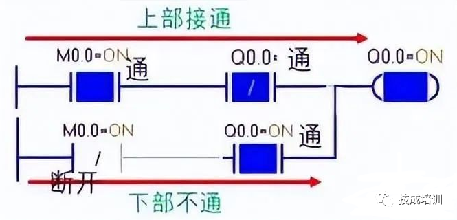
During the first scan cycle, M0.1=1, M0.0=1

Then, in network 2, the upper line — M0.0=1, Q0.0 is initially 0, thus the upper line is connected, making Q0.0 coil=1.
The state of the lower line — M0.0 closed point is 0, Q0.0 open point is 1, thus the lower line is not connected.
The result of the first scan cycle is: M0.1=1, M0.0=1, Q0.0=1. As shown below:
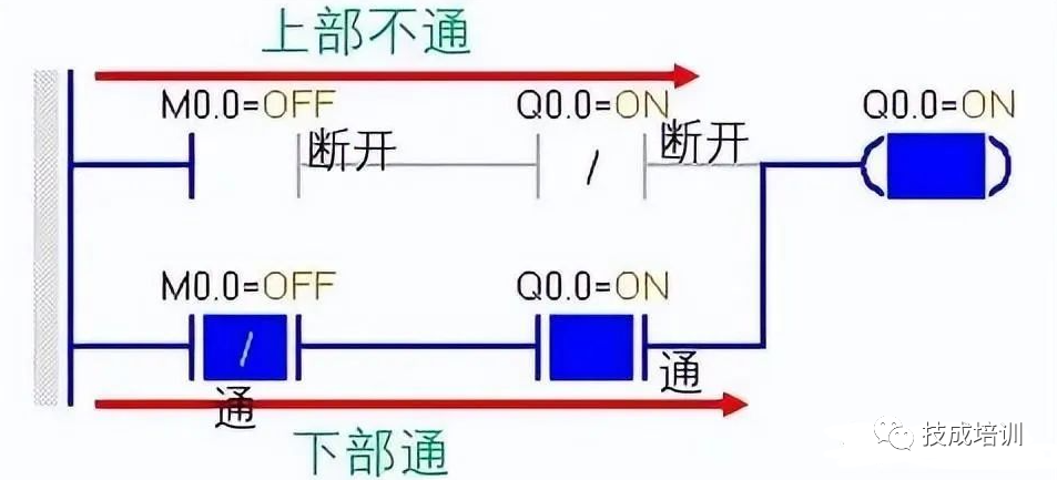
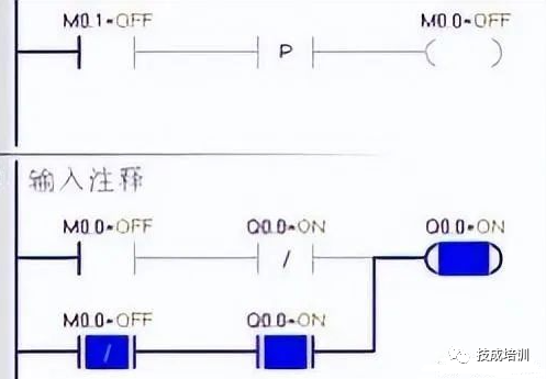
In the second scan cycle, even if M0.1 continues to be on=1, due to the rising edge only connecting for one scan cycle, the P after line is not connected, thus M0.0 is not connected=0, as shown below:

At this time, the state in network 2 becomes:
Upper line: M0.0=0, Q0.0 closed point is not connected, thus the upper line is not connected.
Lower line: M0.0=0, thus the closed point is connected, Q0.0=1, the open point is connected, thus the lower line is connected.
During the third scan cycle, even if M0.1=0 is released, M0.0 continues to be 0, the state in network 2 remains the same as in the second cycle, and Q0.0 continues to be 1.
2. When M0.1=1 is turned on for the second time: the rising edge P connects for another scan cycle.
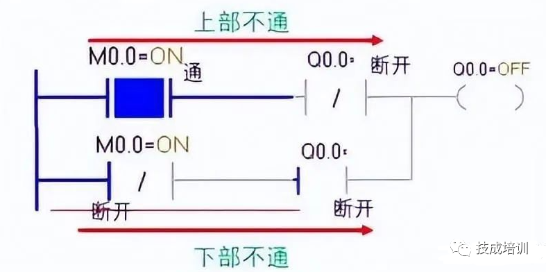
During the first scan cycle: M0.1=1, M0.0=1

In the case where M0.0 is reconnected:
Upper line: M0.0=1 connected, Q0.0 closed point continues to remain open, thus the upper line is not connected.
Lower line: M0.0 closed point is not connected, thus the lower line is not connected. Q0.0 loses power,
therefore, the Q coil is not connected.
During the second scan cycle, even if M0.1 continues to be on=1, due to the rising edge only connecting for one scan cycle, the P after line is not connected, thus M0.0 is not connected=0.
In network 2, the upper line: M0.0=0, Q closed point is connected=1, thus the upper line is not connected.
Lower line: M0.0 closed point is connected, Q open point is disconnected, thus the lower line is not connected.
As shown below:
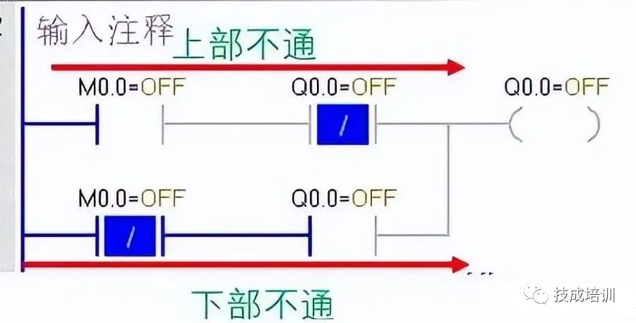
During the third scan cycle: releasing M0.1=0, M0.0 is 0.
The states of the upper and lower lines are the same, and Q is also in a de-energized state.
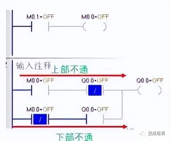
The reason why this single-button start-stop can be successfully achieved is mainly due to the application of the rising edge. Each time it is connected, it can only scan for one cycle. If the rising edge P is removed, this function will output chaotically, failing to achieve alternating output and shutdown.Utilizing the characteristics of scanning execution allows for correct analysis of the program’s actions and drawing of this program.
(Source: Jicheng Training)
『This article is copyrighted by the original author. If there is any infringement, please contact for deletion.』
Editor: Hu Ying
Proofreader: Duan Shaomin
Reviewer: Li Guoqing