Siemens Comprehensive + TIA Portal + EPLAN Electrical Drawing Video Recordings for Sale at Low Price!
Chuangkong Education Siemens Comprehensive Course Introduction
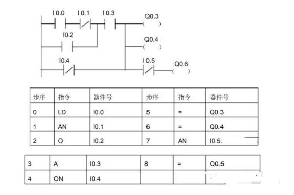
For those just starting with PLCs, mastering and becoming familiar with programming languages is one of the basic conditions formed by instructions. Regardless of how different your programming habits are from others, you must learn this element of instructions, as programming cannot be separated from its components. Next, let’s take a look at the application aspects of these instructions.1. Standard Contact InstructionsLD is the normally open contact instruction, indicating a normally open contact connected to the input bus, i.e., the start of normally open contact logic operation.LDN is the normally closed contact instruction, indicating a normally closed contact connected to the input bus, i.e., the start of normally closed contact logic operation.A is used with normally open contact instructions for series connection of a single normally open contact.AX is used with normally closed contact instructions for series connection of a single normally closed contact.O is used with normally open contact instructions for parallel connection of a single normally open contact.ON is used with normally closed contact instructions for parallel connection of a single normally closed contact.The variable data types in the contact instructions LD, LDN, A, AN, O, and ON are Boolean (BOOL) type. LD and LDN instructions are used to connect contacts to the bus, while A, AN, O, and ON instructions can be reused multiple times. However, when needing to connect more than two contacts in series, the OLD instruction mentioned later must be used.
Example:
SIMATIC Basic Instruction Summary for S7-200:
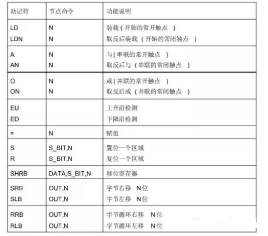
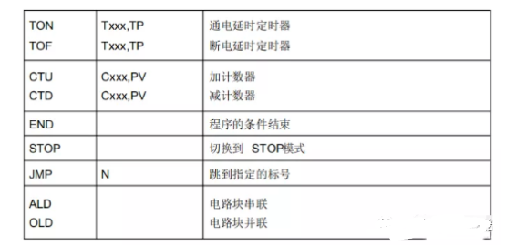
2. Parallel Connection Instruction for Series Circuit Blocks OLDA circuit block with two or more contacts connected in series is called a series circuit block. When connecting series circuit blocks in parallel, the branch starts with LD or LDN instructions and ends with the OLD instruction. The OLD instruction and the ALD instruction mentioned later are both targetless instructions, and both targetless instructions have a step length of one program step. OLD is sometimes also referred to as a block instruction.3. Series Connection Instruction for Parallel Circuits ALDA circuit with two or more contacts in parallel is called a parallel circuit block. When the branch circuit is connected in series with the previous circuit, the ALD instruction is used. The starting point of the branch uses LD or LDN instructions, and after the parallel circuit ends, the ALD instruction is used to connect in series with the previous circuit. The ALD instruction is also referred to as a block instruction and is a targetless instruction, serving as a program step instruction.4. Output Instruction =1. The = output instruction directly connects the coils of relays, timers, counters, etc., to the right side of the ladder diagram’s bus. No contacts are allowed on the right side of the coil. In programming, contacts can be reused, and their types and quantities are not limited.5. Set and Reset Instructions S, RS is the set instruction, which keeps the action; R is the reset instruction, which resets the operation. The registers from a designated position for N points are set or reset, where N=1 to 255. If the designated reset is for a timer or counter bit, it will clear the current value of the timer or counter.6. Edge Trigger Contacts EU, EDThe positive edge contact detects a positive edge (the input signal of the contact goes from 0 to 1), or the negative edge contact detects a negative edge (the input signal of the contact goes from 1 to 0), connecting the contact for one scan cycle. The symbols for positive/negative edges are EU and ED, which have no operands; the symbols “P” and “N” in the contact symbols represent positive and negative edges, respectively.7. No Operation Instruction NOPThe NOP instruction is a no-action, targetless program step instruction. The no-operation instruction makes that step a no-operation. The NOP instruction can replace written instructions and change the circuit. Adding the NOP instruction in the program can reduce changes in step numbers when modifying or adding to the program.8. Program End Instruction ENDEND is a targetless program step instruction. The PLC repeatedly performs input processing, program calculation, and output processing. By writing the END instruction at the end of the program, it indicates the program’s end, directly proceeding to output processing. During program debugging, END instructions can be inserted segmentally, allowing sequential checks of the actions of each program segment. Using the END instruction divides the program into several segments, and after confirming the correctness of the actions in the previous circuit block, the END instructions can be removed sequentially. Note that when executing the END instruction, the monitoring clock is also refreshed.(Content sourced from the internet, copyright belongs to the original author)Disclaimer: If copyright issues arise, please contact for removal!No individual or organization bears related legal responsibilities.
- Siemens Comprehensive + TIA Portal + EPLAN Electrical Drawing Video Recordings for Sale at Low Price!
- Chuangkong Education Siemens Comprehensive Course Introduction
-