Siemens All-in-One + TIA Portal + EPLAN Electrical Drawing Videos for Sale at Low Prices!
Chuangkong Education Siemens All-in-One Course Introduction
The development of PLCs is mainly used for sequential control, using combinations of timers, counters, etc., to replace traditional control systems. PLCs with function instructions have a broader usage value and range. Therefore, this chapter introduces the concept of function instructions.
Representation of Function Instructions:
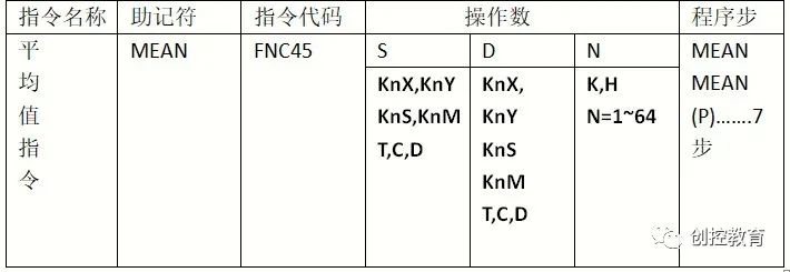
An instruction consists of an instruction name and an instruction code (also called a function number), with different function numbers for different function instructions. Each instruction also has multiple operands: S indicates the source operand, D indicates the destination operand, and n represents constants that may be used in the instruction. The size of an instruction is represented by its program step during execution.
Instruction Execution Forms:
Pulse Execution Type
Continuous Execution Type
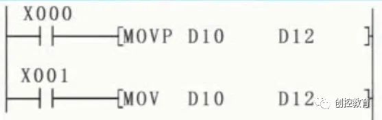
For example, in the ladder diagram shown, MOVP indicates pulse execution type. When we press X000, it transfers data from D10 to D12, but regardless of how long X000 is activated, this instruction only executes once.
If it is a MOV instruction, when we press X001, this instruction will transfer data from D10 to D12 during each scanning cycle.
Bit Soft Elements, Combined Bit Elements, and Word Elements:
Elements that only handle ON/OFF states are called bit soft elements, such as X, Y, S, etc. Other elements that handle numeric data, such as T, C, D, V, Z, etc., are called word soft elements. Bit elements are combined with the first element number of Kn and can also handle numeric data, forming word elements, referred to as combined bit elements or bit element combinations.
The combination rule for combined bit elements is to group them into units of 4 bits. K1~K4 is for 16-bit operations, and K5~K8 is for 32-bit operations. For example, K1XO indicates the 4 bits from X3 to X0, with X0 being the least significant bit. K4M10 indicates the 16-bit combination from M25 to M10, with 10 being the least significant. KBM100 indicates the 32-bit combination from M131 to M100, with M100 being the least significant.
BCD Conversion Instruction:
To facilitate understanding, we will display it in tabular form:
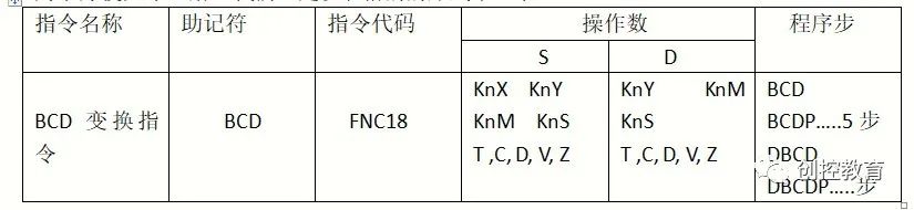
Instruction Format:
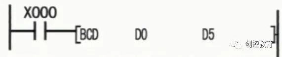
This instruction indicates that when X000 is activated, it converts the binary code in D0 to BCD code and then sends it to D5. Here, it is worth noting that BCD code is also known as binary-coded decimal or bi-decimal code. It uses a 4-bit binary number to represent one decimal digit from 0 to 9.
BIN Code Conversion Instruction:
We will display it in tabular form:
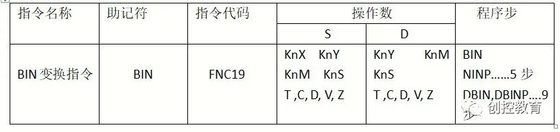
This instruction indicates converting BCD code to binary code.
PLC External Digital Switch:
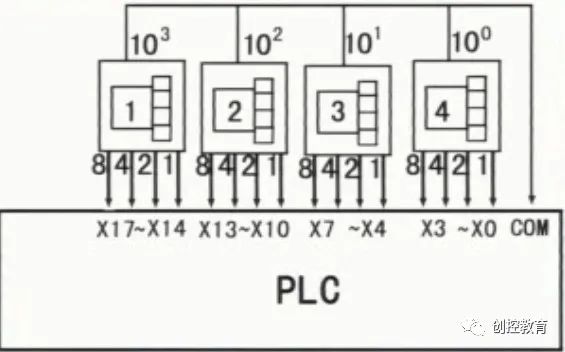
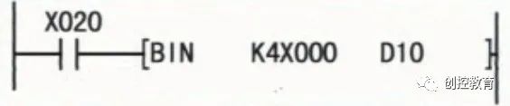
This digital switch is connected to X0~X17. If we want to convert the numbers 1234 from this digital switch, we will use the following instruction. When we press X020, the BCD code in K4X000 will be converted to binary code and stored in D10.
Next, we will use an example to illustrate how to program using these function instructions:
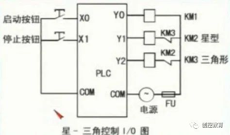
Using Transfer Instructions to Write a Star-Delta Soft Start:
Star-Delta Control I/O Diagram:
PLC Ladder Diagram:
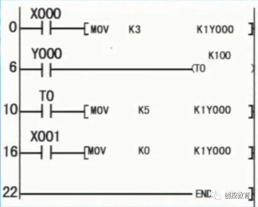
When we press X000, MOV is the transfer instruction, transferring data from K3 to K1Y000. K3 in binary is 0011, so the data in K1Y000 also becomes 0011, turning Y0 and Y1 ON, and the motor starts in star mode. After a 10-second delay, T0 closes, transferring data from K5 to K1Y000. K5 in binary is 0101, so the data in K1Y000 becomes 0101, keeping Y0 ON, Y1 OFF, and Y2 ON, so the motor runs in star mode at this point. When we press X000, K0 transfers data to K1Y000. K0 in binary is 0000, turning off Y0, Y1, and Y2, stopping the motor.
(Content sourced from the internet, copyright belongs to the original author)
Disclaimer: If there are copyright issues, please contact for removal!No individual or organization bears any related legal responsibility.
Siemens All-in-One + TIA Portal + EPLAN Electrical Drawing Videos for Sale at Low Prices!
Chuangkong Education Siemens All-in-One Course Introduction