Currently, there are 5 standard programming languages for PLCs, including graphical programming languages and textual programming languages.
Graphical programming languages include:
Ladder Diagram (LD);
Function Block Diagram (FBD);
Sequential Function Chart (SFC).
Textual programming languages include:
Instruction List (IL) & Structured Text (ST).
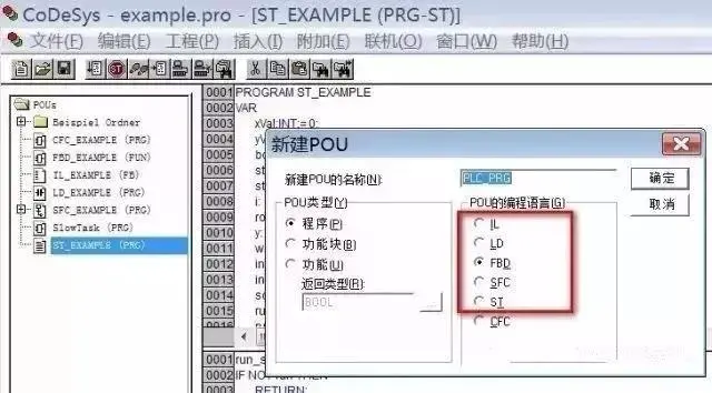 The programming languages of IEC 1131-3 are a set of international programming language standards for industrial control systems, formed based on the reasonable absorption and reference of programming languages from PLC manufacturers worldwide by the IEC working group. They are not only applicable to PLC systems but also to a broader range of industrial control fields, making significant contributions to the global standardization of PLC programming languages.
Ladder Diagram (LD)
Ladder Diagram (LD) is the first programming language adopted by PLCs and is also the most widely used programming language in PLCs. The ladder diagram programming language evolved from the schematic diagrams of relay control systems, maintaining the basic ideas of relay control system ladder diagrams, with some differences in symbols and expressions.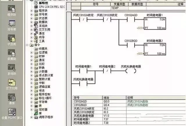 The original intention of PLC design was for use by electrical technicians in factory workshops, to align with the thinking habits of relay control circuits. As the first programming language used in PLCs, ladder diagrams retained the style and habits of relay circuit diagrams, making it the most easily accepted and used language by electrical technicians.1. Soft RelaySome programming elements in PLC ladder diagrams retain the name of relays, such as input relays, output relays, and internal auxiliary relays, but they are not real physical relays; instead, they are storage units (soft relays), with each soft relay corresponding to a storage unit in the PLC memory image register.If the storage unit is in the “1” state, it indicates that the corresponding soft relay coil in the ladder diagram is “energized,” with its normally open contact closed and normally closed contact open, referred to as the “1” or “ON” state of that soft relay.If the storage unit is in the “0” state, the corresponding soft relay coil and contact states are the opposite of the above, referred to as the “0” or “OFF” state of that soft relay. These “soft relays” are often referred to as programming elements.2. Power FlowThere is an imaginary “conceptual current” or “Power Flow” that flows from left to right, consistent with the order of logical operations when executing user programs.Power flow can only flow from left to right. Utilizing the concept of power flow can help us better understand and analyze ladder diagrams.3. Bus BarThe vertical common lines on both sides of the ladder diagram are called bus bars.When analyzing the logical relationships in ladder diagrams, one can imagine a DC power supply voltage with positive on the left and negative on the right between the left and right bus bars, with “power flow” flowing from left to right. The right bus bar can be omitted.
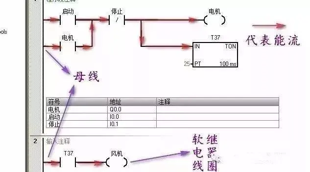 4. Logical Calculation of Ladder DiagramsBased on the states of various contacts in the ladder diagram and their logical relationships, the states of the programming elements corresponding to the coils in the diagram are determined, referred to as the logical calculation of the ladder diagram.Logical calculations in ladder diagrams are performed in a left-to-right, top-to-bottom order. The results of the calculations can immediately be utilized by subsequent logical calculations.Logical calculations are based on the values in the input image registers, rather than the instantaneous states of external input contacts.1. Corresponds to the electrical operation principle diagram, with intuitiveness and correspondence; 2. Consistent with the original relay logic control technology, making it easy for electrical technicians to master and learn; 3. The difference from the original relay logic control technology is that the power flow in the ladder diagram is not actual current, and the internal relays do not actually exist, so when applying, one must distinguish these concepts from the original relay logic control technology; 4. There is a one-to-one correspondence with instruction list programming languages, facilitating mutual conversion and program checking.
Function Block Diagram (FBD)
Function Block Diagram (FBD) uses graphical symbols similar to digital logic gate circuits, making logic intuitive and easy to use. It has instructions equivalent to contacts and coils in ladder diagram programming, capable of solving a wide range of logical problems.1. Based on functional modules, starting from control functions, making the analysis and understanding of control schemes easier;2. Functional modules describe functions graphically, greatly facilitating programming and configuration for designers, with good operability;3. For larger control systems with complex control relationships, the relationships of control functions can be clearly expressed, thus reducing programming and configuration time, as well as debugging time.
Sequential Function Chart (SFC)
Sequential Function Chart (SFC) is also known as flowchart or state transition diagram, a graphical functional description language specifically designed for describing industrial sequential control programs, allowing programming for systems with complex structures such as concurrency and selection.1. Focused on functionality, clearly organized, facilitating understanding and communication of program operations; 2. For large programs, it allows for division of design work, adopting a more flexible program structure, saving programming and debugging time; 3. Commonly used in large-scale systems with complex program relationships; 4. Only when the commands and operations of active steps are executed, the transitions after the active steps are scanned, thus significantly reducing the overall scanning time compared to other program compilation methods.
Instruction List (IL)
Instruction List (IL) is a programming language similar to mnemonic assembly language in computers, being the most basic programming language for programmable controllers. Instruction list programming uses one or several easily memorable characters to represent a certain operational function of the programmable controller.1. Uses mnemonics to represent operational functions, making it easy to remember and master; 2. Uses mnemonics on the programmer’s keyboard, making it convenient for operation, allowing programming design without a computer; 3. Has a one-to-one correspondence with ladder diagrams, with characteristics similar to ladder diagram languages.
Structured Text (ST)
Structured Text (ST) is a high-level textual language that can describe functions, function blocks, and program behaviors, and can also describe steps, actions, and transitions in sequential function flowcharts.Structured text language superficially resembles PASCAL language, but it is a programming language specifically developed for industrial control applications, with strong programming capabilities for variable assignments, callback functions, function blocks, creating expressions, writing conditional statements, and iterative programs.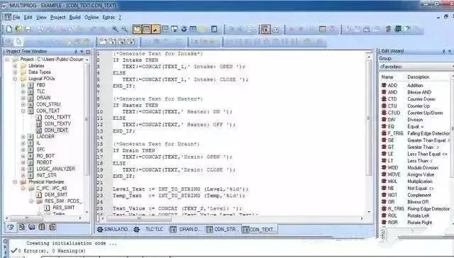 1. Uses high-level languages for programming, capable of completing more complex control calculations; 2. Requires a certain level of knowledge in advanced computer programming languages and programming skills, with higher skill requirements for programmers, making it difficult for ordinary electrical personnel to complete; 3. Performance in terms of intuitiveness and ease of operation is relatively poor; 4. Often used for implementing control functions that are difficult to achieve with other languages such as function blocks.Note: Not all PLCs support all programming languages (for example, many low-end PLCs do not support function block diagrams and sequential function charts), while large PLC control systems generally support these 5 standard programming languages or similar programming languages.
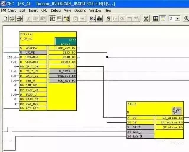 There are also some programming languages outside the standard that, although not included in the standard languages, have been developed for specific applications and may be better programming languages in certain situations.For example, the Continuous Function Chart (CFC) of D7-SYS was developed specifically for large continuous process control, allowing easy implementation of a series of special functions such as PID controllers, counters, positioners, ramp function generators, etc., simply by calling the CFC function blocks in the program, without requiring specialized programming knowledge, just a basic understanding of graphical processing and standard program block usage for simple settings.Discussing PLC Learning Methods1. Learning PLC programming requires strong willpower and sufficient patienceEveryone has their strengths. Some see programming as a tedious and lengthy task; others view it as an interesting intellectual game. If you are the former, it is strongly advised to stay away from this job.After all, programming work is a challenge to one’s willpower and patience, requiring numerous trials and errors, debugging-modifying-debugging-modifying… After countless failures, when you see the PLC running in an orderly manner according to your control requirements, you will feel a great sense of achievement, akin to clearing a level in a game.2. Learning PLC programming requires confidence to practiceMany beginners often hesitate, fearing damage to equipment, and are reluctant to perform practical operations. In fact, these fears are unfounded; as long as you carefully read the manual and follow standard wiring practices, there should be no issues.Do not worry about whether the program you write will cause problems affecting the normal operation of the PLC; the only way to find out if there are issues with the program is to run the PLC. Therefore, having the confidence to practice boldly is essential for PLC programming.3. Programming requires meticulous logical thinkingProgramming itself is a logical thinking process.The original PLCs were designed to replace relay logic circuits, thus inheriting the description method of using contacts as triggering conditions from relay circuits.In PLCs, virtual contacts replace relay contacts, while the logical relationships expressed by relay circuits are preserved. Therefore, it is essential to clarify the logical relationships between objects and possess meticulous logical thinking.4. Develop good programming habitsEveryone has different habits and characteristics in programming, and uniformity cannot be enforced. However, some good habits should be followed by most people.1. Clarify logical relationships and timing relationships, and create program flowcharts;2. Reasonably allocate main programs, subprograms, and interrupt programs;3. Reasonably allocate registers and create a register symbol table.Many PLC operations directly target registers; if there are unreasonable overlaps in register addresses in the program, it may cause program errors.Creating a register symbol table can not only avoid the above issues but also enhance the readability of the program.PLC provides a wealth of instructions and modules; beginners should try to use simple instructions to achieve their goals, which will help in understanding more complex instructions. After gaining some experience, one should consider mastering the application of complex instructions and optimizing programs.5. Have a certain foundation in program design knowledgeHaving a certain foundation in program design knowledge and understanding the relevant PLC program design theories is important.Without theoretical preparation or guidance in this area, relying solely on practical exploration may be manageable for simple problems, but complex issues become challenging, leading to wasted time and effort without producing high-quality programs, often resulting in inefficiency.Any theory is merely a summary of experience, ultimately derived from practice.