
IntroductionIn the previous article (Getting Started with Zephyr: Saving Data to Files), I demonstrated how to create an application using the Zephyr project RTOS to store data on a microSD card. A microSD card allows embedded systems to store large amounts of data. When there is no internet connection or the cost of frequent data uploads is too high, data can be stored locally. I showed how to mount a microSD card using the exFAT file system and write data to files through Zephyr. Using a popular file system is valuable because it allows data to be transferred to a PC for local retrieval.
In this article, I will demonstrate how to write data to Electrically Erasable Programmable Read-Only Memory (EEPROM). Like microSD cards, EEPROM is also a type of non-volatile storage. However, unlike microSD cards, EEPROM is usually slower and has a smaller capacity. The advantage of EEPROM is that it consumes less power than microSD cards and is cheaper and smaller. It is typically used to store small amounts of data, such as configuration information.
Hardware
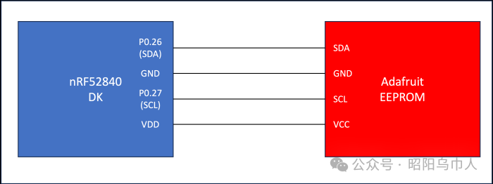
This blog post will use the Nordic nRF52840 development board. We will connect the nRF52840 development board to the Adafruit 24LC32 EEPROM breakout board(https://www.adafruit.com/product/5146). Below is a diagram showing how to connect the Adafruit breakout board to the nRF52840 development board:
Embedded Software
In this section, we will walk through the relevant parts of the embedded software to interface with the Adafruit EEPROM breakout board. First, we can obtain the Zephyr v4.0 version using West by executing the following commands:
$> west init -m <a href="https://github.com/zephyrproject-rtos/zephyr">https://github.com/zephyrproject-rtos/zephyr</a> --mr v4.0.0 zephyrproject$> cd zephyrproject$> west updateSecondly, we can clone the repository containing the test application:
$> git clone https://github.com/mabembedded/zephyr-eeprom.gitFinally, we can connect the nRF52840 development kit to the PC via USB and open the terminal interface. Execute the following commands to build and flash the application:
$> cd zephyr-eeprom$> cmake –preset build$> west build && west flashWe will see the following output in the terminal interface:
*** Booting Zephyr OS build zephyr-v4.0.0 ***Found EEPROM device "eeprom@50"Using eeprom with size of: 4096.Magic = 32323032going to initialize dataDevice booted 0 times.Magic = 1e010000Device booted 218105603 times.Reset the MCU to see the increasing boot counter.We can execute the following command to reset the nRF52840 development kit and rerun the application:
$> nrfjprog --resetWe can see the following output (we expect to see the boot count increase):
*** Booting Zephyr OS build zephyr-v4.0.0 ***Found EEPROM device "eeprom@50"Using eeprom with size of: 4096.Magic = 32323032going to initialize dataDevice booted 0 times.Magic = 1e010000Device booted 218105603 times.Reset the MCU to see the increasing boot counter.Clearly, something needs to be fixed. If we check the source code, we will find that the application’s goal is to identify a region in the EEPROM to store the number of times the MCU has booted. We use a magic value, which is a hard-coded 4-byte value to identify the starting position of this region. If this value is not detected, the magic value initializes the EEPROM and the following byte representing the boot count is initialized to zero. On subsequent boots, the boot count should increment. Clearly, this is not happening, and my next step is to investigate the cause and hope to find a solution.
DEVICETREE OVERLAY
We can open the devicetree overlay to understand how to enable support for the AT24 chip (I detailed devicetree overlays in the article “Getting Started with Zephyr: Devicetree Overlays”):
/ { aliases { eeprom-0 = &at24_eeprom; };};&i2c0 { status = "okay"; at24_eeprom: eeprom@50 { compatible = "atmel,at24"; status = "okay"; reg = <0x50>; size = <4096>; pagesize = <32>; address-width = <8>; timeout = <5>; };};I created an alias at the root node of the devicetree, which is the eeprom-0 node, referenced in the source code. Then, I ensured the main I2C bus was enabled by referencing it and ensuring its “status” property was set to “okay”. Next, I created a node within the I2C bus representing the EEPROM. The compatible property enables the AT24 driver in the Zephyr EEPROM subsystem. This is achieved by linking the Kconfig under drivers/eeprom to the devicetree binding:
config EEPROM_AT24 bool "Atmel AT24 (and compatible) I2C EEPROM support" default y depends on DT_HAS_ATMEL_AT24_ENABLED select I2C select EEPROM_AT2X help Enable support for Atmel AT24 (and compatible) I2C EEPROMs.The “DT_HAS_ATMEL_AT24_ENABLED” macro uses the compatible string to determine whether the AT24 device exists and enables the driver.
The “reg” property sets the I2C address of the EEPROM. The subsequent properties set the relevant values for the chip.
KCONFIG
The Kconfig for this application is quite simple, as shown below:
CONFIG_PRINTK=yCONFIG_EEPROM=yCONFIG_MAIN_STACK_SIZE=2048CONFIG_HEAP_MEM_POOL_SIZE=512CONFIG_GPIO=yThe only relevant configuration option is “CONFIG_EEPROM”.
APPLICATION SOURCE
We use the alias specified in the devicetree in the “get_eeprom_device” function, which returns a device pointer representing the EEPROM chip:
static const struct device *get_eeprom_device(void){ const struct device *const dev = DEVICE_DT_GET(DT_ALIAS(eeprom_0));..}Here, we can see the function uses the devicetree binding macro to retrieve the alias specified in the devicetree. It then ensures the device is ready, and if it is, prints the device name. If not, it returns an error message.
In the main program, we use Zephyr’s EEPROM API calls to perform the necessary operations. First, “eeprom_get_size” is used to get and report the capacity of the EEPROM chip:
eeprom_size = eeprom_get_size(eeprom);printk("Using eeprom with size of: %zu.\n", eeprom_size);Then, we interact with the EEPROM chip using the “eeprom_read” and “eeprom_write” functions:
rc = eeprom_read(eeprom, EEPROM_SAMPLE_OFFSET, &values, sizeof(values));..rc = eeprom_write(eeprom, EEPROM_SAMPLE_OFFSET, &values, sizeof(values));Using the generic API calls of the Zephyr EEPROM subsystem, we do not need to understand the underlying implementation details of specific drivers or hardware. We only need to enable the corresponding device in the devicetree, and the Zephyr build and driver infrastructure will handle the rest.
Conclusion
In this article, I introduced how to implement interaction between a Zephyr application and an EEPROM chip. I demonstrated how to use the devicetree to make Zephyr aware of the chip’s existence and enable the corresponding driver. Then, I showed how to use high-level Zephyr API calls to free us from the underlying implementation details of specific drivers. I hope to help everyone resolve issues that arise in current implementations.