Click the blue “One Click Linux“, and select “Set as Starred“
First time to read valuable articles

☞【Valuable】Embedded Driver Engineer Learning Path
☞【Valuable】Linux Embedded Knowledge Points - Mind Map - Free Access
☞【Employment】A comprehensive Linux IoT project to include in your resume
☞【Employment】Job Resume Template
Author: CSDN Little Shrimp’s Daddy
In this article, we take the IIC controller of the RK board as an example to explain the IIC driver framework under Linux.
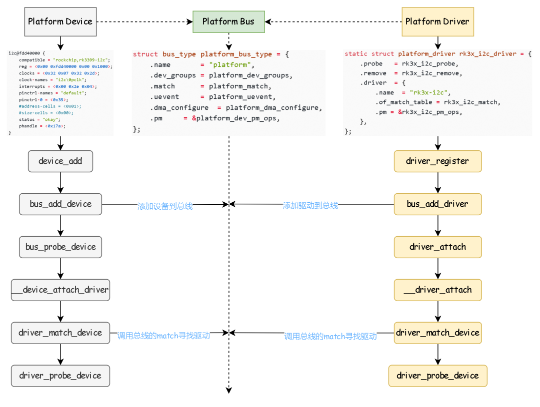
The device tree creates a node for the I2C device, and during the device tree traversal, a platform device for I2C is created:
i2c@fdd40000 { compatible = "rockchip,rk3399-i2c"; reg = <0x00 0xfdd40000 0x00 0x1000>; clocks = <0x32 0x07 0x32 0x2d>; clock-names = "i2c\0pclk"; interrupts = <0x00 0x2e 0x04>; pinctrl-names = "default"; pinctrl-0 = <0x35>; #address-cells = <0x01>; #size-cells = <0x00>; status = "okay"; phandle = <0x17a>; }The device contains the following information:
-
compatible: Compatibility, used to match the driver that can be used for this device;
-
reg: The register base address and range of this device;
-
interrupts: Interrupt configuration used by the I2C interrupt controller;
This platform device will match the corresponding platform driver when placed on the platform bus, so let’s first look at what the platform bus is:
struct bus_type platform_bus_type = { .name= "platform", .dev_groups= platform_dev_groups, .match= platform_match, .uevent= platform_uevent, .dma_configure= platform_dma_configure, .pm= &platform_dev_pm_ops, };We only focus on the match function, which is called when a new device or a new driver is added to this bus. When a new device is added, the match function is used to match the corresponding driver, and when a new driver is added to this bus, the match function is also used to match the device.
Taking the I2C platform bus driver of the RK board as an example, we first find the I2C platform bus driver for the RK board:
static struct platform_driver rk3x_i2c_driver = { .probe = rk3x_i2c_probe, .remove = rk3x_i2c_remove, .driver = { .name = "rk3x-i2c", .of_match_table = rk3x_i2c_match, .pm = &rk3x_i2c_pm_ops, }, };Using the of_match_table to match the corresponding device, and using probe to initialize the device.
The overall process is as follows:
Before delving into the IIC driver code, let’s first take a brief look at the entire data sending and receiving process of IIC. This will not involve the timing of the underlying hardware, which readers need to learn themselves.
The IIC master writes data to the slave:
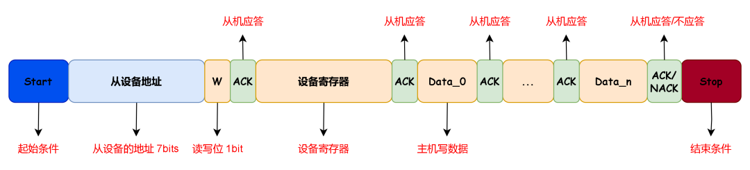
The IIC master reads data from the slave:

Of course, IIC’s sending and receiving is not limited to the two modes mentioned above; here we only discuss the two commonly used methods for sending and receiving data.
Next, we start analyzing the IIC platform driver code:
Taking the RK board as an example, the bus driver code is located in: drivers\i2c\busses\i2c-rk3x.c. For specific implementations, you can refer to my previous articles; here I will only provide an overall block diagram. The I2C controller will also be exposed to user space as a character device node, allowing us to communicate with the corresponding I2C peripherals through the I2C controller’s character device.
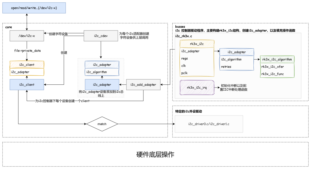
Now let’s take a look at the overall flowchart when the user layer opens a character device node corresponding to an I2C controller:
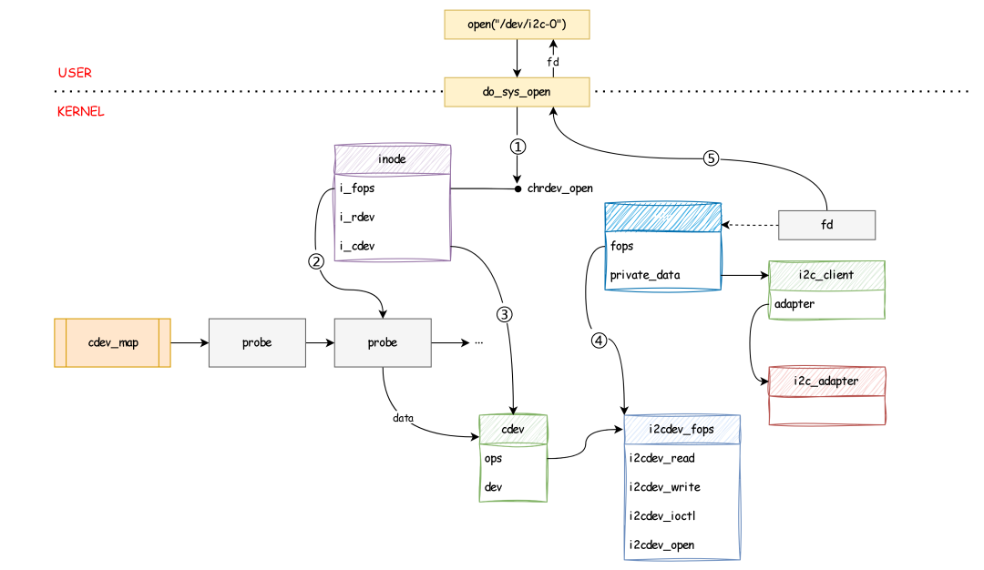
The entire process is as follows:
When an application program opens a device file, it enters the kernel through the system call sys_open,
In the kernel space, do_sys_open is responsible for initiating the entire device file opening operation,
First, it obtains the inode corresponding to the device file, then calls the i_fop function, for character devices, the i_fop function is chrdev_open,
The latter looks up the device object cdev corresponding to the device in cdev_map through the i_rdev member in the inode,
After successfully finding the device object, it points the cdev member of the inode to the character device object, so that the next time the device file node is opened, the character device object corresponding to the device node can be directly obtained through the i_cdev member.
Every time the kernel opens a device file, it generates an integer file descriptor fd and a new struct file object filp to track this operation,
When opening the device file, the kernel associates filp and fd, and assigns the ops in cdev to filp->f_op, while creating i2c_client, associating i2c_adapter, and linking filp’s private_data with i2c_client.
Finally, the sys_open system call returns the device file descriptor fd to user space.
Next, let’s use a practical example to understand the process of a completed Combined R/W operation for IIC:
User-side example code is as follows:
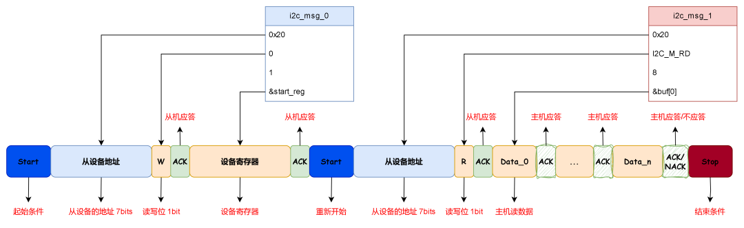
int main(void){ int fd = 0; int ret = 0; const char *path_name ="/dev/i2c-0"; uint8_t buf[8] = {0}; uint8_t start_reg = 0x0; struct i2c_msg read_msg[2] = { { 0x20, /* slave addr */ 0, /* operate flags */ 1, /* data len */ &start_reg /* data buf */ }, { 0x20, /* slave addr */ I2C_M_RD, /* operate flags */ 8, /* data len */ &buf[0] /* data buf */ }, }; struct i2c_rdwr_ioctl_data rdwr = { .msgs = read_msg, .nmsgs = 2 }; fd = open(path_name, O_RDWR); ret = ioctl(fd, I2C_SLAVE_FORCE, 0x20); ret = ioctl(fd, I2C_RDWR, (unsigned long)&rdwr); return 0; }This is a Combined slave data read operation, consisting of two parts of i2c_msg. The first msg writes the device register address to the slave, indicating the device register to be read, and then sends a read data request to request 8 bytes of data from the slave.
The corresponding entire IIC protocol segment is as follows:
Then we enter the kernel through ioctl and ultimately call i2cdev_fops->i2cdev_ioctl.
static const struct file_operations i2cdev_fops = { ... .compat_ioctl= compat_i2cdev_ioctl, ... }; static long i2cdev_ioctl(struct file *file, unsigned int cmd, unsigned long arg) { struct i2c_client *client = file->private_data; ... switch (cmd) { ... case I2C_RDWR: { ... return i2cdev_ioctl_rdwr(client, rdwr_arg.nmsgs, rdwr_pa); } ... return 0; } static noinline int i2cdev_ioctl_rdwr(struct i2c_client *client, unsigned nmsgs, struct i2c_msg *msgs) { ... res = i2c_transfer(client->adapter, msgs, nmsgs); ... return res; } int i2c_transfer(struct i2c_adapter *adap, struct i2c_msg *msgs, int num) { ... ret = __i2c_transfer(adap, msgs, num); return ret; } int __i2c_transfer(struct i2c_adapter *adap, struct i2c_msg *msgs, int num) { ... ret = adap->algo->master_xfer(adap, msgs, num); ... return ret; }It can be seen that the final call is to master_xfer in the i2c_adapter.

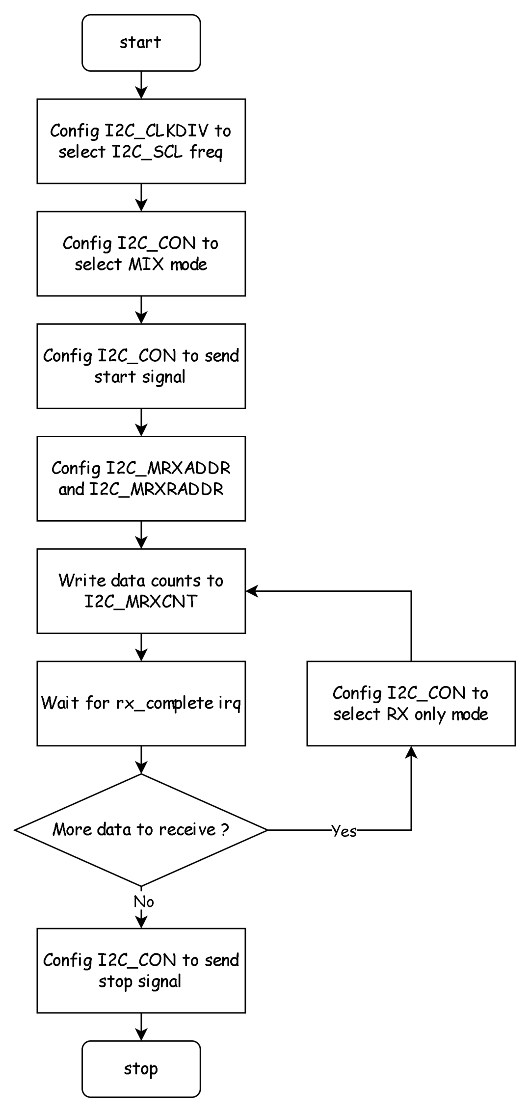
static int rk3x_i2c_xfer(struct i2c_adapter *adap, struct i2c_msg *msgs, int num) { struct rk3x_i2c *i2c = (struct rk3x_i2c *)adap->algo_data; ... for (i = 0; i < num; i += ret) { ret = rk3x_i2c_setup(i2c, msgs + i, num - i); ... rk3x_i2c_start(i2c); ... } ... }In rk3x_i2c_xfer, the MRXADDR and MRXRADDR registers are initialized and the state machine state of the I2C is initialized.
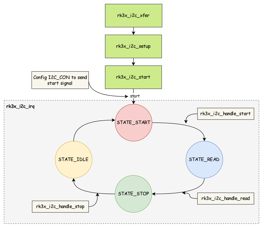
Then, the start signal is sent to begin the entire I2C process through rk3x_i2c_start, and the entire I2C data sending and receiving state machine is maintained in rk3x_i2c_irq:
static irqreturn_t rk3x_i2c_irq(int irqno, void *dev_id) { ... switch (i2c->state) { case STATE_START: rk3x_i2c_handle_start(i2c, ipd); break; case STATE_WRITE: rk3x_i2c_handle_write(i2c, ipd); break; case STATE_READ: rk3x_i2c_handle_read(i2c, ipd); break; case STATE_STOP: rk3x_i2c_handle_stop(i2c, ipd); break; case STATE_IDLE: break; } ... }The flowchart and state machine in Combined W/R mode are shown below:
Flowchart:
IIC Driver State Machine:
Here we have briefly introduced the IIC driver framework and its workflow under Linux. To understand it in depth, you need to read the driver code yourself.
Original link: https://blog.csdn.net/cxjczy1990/article/details/144853176end
One Click Linux
Follow, reply 【1024】 to receive a wealth of Linux materials
Collection of Wonderful Articles
Recommended Articles
☞【Album】ARM☞【Album】Fan Q&A☞【Album】All Originals☞【Album】LinuxIntroduction☞【Album】Computer Network☞【Album】Linux Driver☞【Valuable】Embedded Driver Engineer Learning Path☞【Valuable】All Knowledge Points of Linux Embedded – Mind Map