
Source: cnblogs.com | Author: Jayant Tang

The Zephyr Project is an Apache 2.0 open-source project launched by the Linux Foundation, with a very friendly copyright, suitable for commercial project development. It includes an RTOS, a build system, and various third-party libraries. Most examples in NCS run on the Zephyr RTOS.
For developers who have previously only been exposed to the IDE + peripheral driver library development approach, the configuration and build system of Zephyr may be somewhat confusing, but once you master it, you will find its convenience.
This article continues from the previous part and will further introduce the configuration and build tools in NCS, including Zephyr’s unique Sysbuild, Boards, and the Partition Manager for memory partitioning provided by Nordic.
【Nordic Blog Series】Understanding Zephyr Build and Configuration System (Part 1)
Sysbuild (System Build)
The previously introduced CMake, Kconfig, and DeviceTree are configuration tools widely used in other fields (such as the Linux kernel). However, Sysbuild is a newly introduced build mechanism in Zephyr; it is a high-level configuration tool that addresses the issue of multi-image compilation for MCUs.
The tools mentioned earlier are used for compiling a single image. When we need to compile firmware with multiple images, there may be some differences in configuration items between these different images.
For example, I want my serial port to be used for logging, but in the bootloader image, the same serial port is used for firmware upgrades.
Another example is that I have chosen an external QSPI Flash that differs from the Flash on the Nordic official development board, so I modified the overlay file in my project. However, I also need to modify the overlay file in the bootloader project somewhere so that the bootloader can recognize my Flash.
The above describes the configuration differences between different images running on the same CPU. In addition, there are identical configurations between different images running on different CPUs; for example, on a dual-core MCU, I want to configure both the App Core and Net Core to be in debug mode or release mode simultaneously, rather than tuning them separately.
1
Sysbuild Switch
You can decide whether to use Sysbuild during compilation
west build --sysbuild
west build --no-sysbuild
After NCS v2.7.0, the west build command defaults to enabling –sysbuild. In NCS v2.6.x and earlier, it is disabled by default.
2
Namespace
In the multi-image compilation scenario, when we use west build for command-line compilation, if we want to add some configuration items, we may need to specify which sub-project this configuration item belongs to or if it belongs to the overall (Sysbuild).
# Kconfig with Namespace-D<namespace>_CONFIG_<var>=<value>
# CMake options with Namespace-D<namespace>_<var>=<value>
For example:
west build -b reel_board --sysbuild samples/hello_world \
 -- \
 -DSB_CONFIG_BOOTLOADER_MCUBOOT=y \
 -DCONFIG_DEBUG_OPTIMIZATIONS=y \
 -Dmcuboot_CONFIG_DEBUG_OPTIMIZATIONS=y# Pass CONFIG_BOOTLOADER_MCUBOOT=y to Sysbuild (global), indicating to use bootloader as MCUBOOT, namespace is SB# Pass CONFIG_DEBUG_OPTIMIZATIONS=y to the current default Application project, namespace is empty# Pass CONFIG_DEBUG_OPTIMIZATIONS=y to the mcuboot project, namespace is mcuboot, which is the name of the sub-project
3
Sysbuild Configuration Files
In addition to the method of passing compilation options during compilation mentioned above, you can also save Sysbuild-level configuration files
application/
├── ...
├── CMakeLists.txt # CMake for the application
├── prj.conf       # Configuration items for the application
├── ...
├── Kconfig.sysbuild # Sysbuild global-level Kconfig menu definition. Can be omitted; if omitted, the default menu in the SDK is used
├── sysbuild.conf    # Sysbuild global configuration items
├── ...
├── sysbuild.cmake   # Sysbuild global-level CMake. Can be used to manage which project images participate in the overall image compilation
├── ...
└── sysbuild/         # Under the Sysbuild directory, you can configure each sub-project separately
    └── mcuboot
        ├── prj.conf
        ├── app.overlay
        └── boards
            ├── <board_A>.conf
            ├── <board_A>.overlay
            ├── <board_B>.conf
            └── <board_B>.overlay
For examples of sysbuild, refer to several examples under zephyr/samples/sysbuild/.
4
Sysbuild Configuration Files
Refer to zephyr/samples/sysbuild/hello_world; this project is used for dual-core MCU operation. The App Core runs a Hello World, and then another Hello World project is added for the other core. Finally, dual-image firmware is compiled.
To add a sub-project to the current project, it is essentially modifying sysbuild.cmake.
ExternalZephyrProject_Add(  APPLICATION my_sample                 # Name of the project to be added  SOURCE_DIR <path-to>/my_sample        # Path of the project to be added  BOARD mps2_an521_remote               # If necessary, specify the board used by the project to be added  BUILD_ONLY TRUE                       # If necessary, compile only without flashing)
# Compile my_sample first, then compile the current default application project
sysbuild_add_dependencies(CONFIGURE ${DEFAULT_IMAGE} my_sample)# Equivalent to the standard CMake function add_dependencies(${DEFAULT_IMAGE} my_sample)
# Flash my_sample first, then flash the current application project
sysbuild_add_dependencies(FLASH ${DEFAULT_IMAGE} my_sample)# If my_sample is configured as BUILD_ONLY=TRUE, an error will occur
Specifically, if the project to be added is MCUBOOT, you only need to add the following configuration in sysbuild.conf:
SB_CONFIG_BOOTLOADER_MCUBOOT=yBecause the SDK has already written the sysbuild related to MCUBOOT, you can enable it directly.
[Deprecated] Parent-child Image
In versions of NCS v2.6.x and earlier, multi-image management relied on the parent-child image. This tool is not from Zephyr, but from Nordic. It can also manage the configuration of sub-images separately in a sub-folder. However, its difference from Sysbuild is that it does not have a separate high-level global configuration. This leads to some configurations that should actually belong to the global being placed directly in the Application-level configuration (for example, selecting which bootloader), which can occasionally cause confusion.
If you are using an older version of NCS, it is recommended to refer to the documentation regarding this aspect: https://docs.nordicsemi.com/bundle/ncs-2.7.0/page/nrf/config_and_build/multi_image.html
Partition Manager Memory Partition File
Managing the memory partition of an MCU is a common need. It needs to be managed not only in multi-image and OTA scenarios but also when mounting file systems on internal and external flash, storing production information in separate partitions, and so on.
For memory partition files, especially those with external flash, you can refer to the Matter example, such as nrf/samples/matter/lock. You can see many pm_static_xxx.yml:
mcuboot:  address: 0x0  size: 0x7000  region: flash_primary
mcuboot_pad:  address: 0x7000  size: 0x200
app:  address: 0x7200  size: 0xefe00
mcuboot_primary:  orig_span: &id001  - mcuboot_pad  - app  span: *id001  address: 0x7000  size: 0xf0000  region: flash_primary
mcuboot_primary_app:  orig_span: &id002  - app  span: *id002  address: 0x7200  size: 0xefe00
factory_data:  address: 0xf7000  size: 0x1000  region: flash_primary
settings_storage:  address: 0xf8000  size: 0x8000  region: flash_primary
mcuboot_secondary:  address: 0x0  size: 0xf0000  device: MX25R64  region: external_flash
external_flash:  address: 0xf0000  size: 0x710000  device: MX25R64  region: external_flash
The detailed syntax does not need to be focused on; different projects are basically similar.
Note: When configuring the Partition Manager, be sure to align the Flash Page!!!
1
Static Partition File Description
MCUBoot Related
MCUBoot related can be copied directly, just modify the address and size.
-
mcuboot: This is the firmware size of MCUBoot. The Matter MCUBoot configuration is specially optimized in the SDK, so it only needs 0x7000 bytes. Generally, adding a space of 0xc000 is needed.
-
mcuboot_pad: During DFU, store some flags and verification information about firmware upgrades.
-
mcuboot_primary: This is the slot where the app is located, and it also has mcuboot_pad.
-
mcuboot_secondary: This is the slot where the new firmware is stored during upgrades. Usually, the app is responsible for receiving the new firmware, then jumping to MCUBoot, which performs partition firmware swapping, completing the upgrade. The secondary slot can also be placed in external flash.
App Related
App related can be copied directly, just modify the address and size.
-
app and mcuboot_primary_app: Both are app partitions.
Settings Storage
Settings_storage is a partition for storing configuration items in the Zephyr system, which is a simple file system. It can use “strings” (usually file paths, such as id/serial) as handles to access data (providing start address and length).
Many libraries in Zephyr rely on Settings to store persistent data, such as Bluetooth binding keys. Therefore, this partition is very common. Considering that many components use Settings, it is best not to place Settings in external flash; otherwise, if external flash goes to low power mode while some component needs Settings, an error will occur, which is very troublesome.
Since Settings is a file system, it does not store data at a single address but continuously writes backward until the partition flash is full, then erases all previous pages for garbage collection. Therefore, it is best to prepare at least 2 pages of flash space for settings_storage (the above example is 0x8000, which is for two 4kB pages). If in specific extreme peak conditions, flash read and write are very fast and numerous, then 3 pages or more may be needed. For example, during HomeKit certification with 16 tests of cyclic Bluetooth binding, 3 pages are required.
Other Partitions
There is nothing special about other partitions; just define a label to name a partition.
-
factory_data: In the Matter project, this partition is used to store certificates and other data.
-
external_flash: The remaining position in the external flash, named arbitrarily.
In fact, the Partition Manager is just a set of scripts, and it ultimately needs to be implemented in C code. In the code, you can access these partitions through labels. For example, in the Matter SDK, it will access authentication certificates and other data through factory_data.
You can also make full use of this unused partition. Use macros defined in nrf/include/flash_map_pm.h to convert these labels into Flash Device handles and partition handles that Zephyr can use. For example, use this external_flash partition to establish an NVS file system.
#include <zephyr/storage/flash_map.h>
#define NVS_PARTITION    external_storage
#define NVS_PARTITION_DEVICE  FIXED_PARTITION_DEVICE(NVS_PARTITION)
#define NVS_PARTITION_OFFSET  FIXED_PARTITION_OFFSET(NVS_PARTITION)
#include <zephyr/fs/nvs.h>
static struct nvs_fs fs;
int app_nvs_entry(void){
    int rc = 0;
    char buf[16];
    uint8_t key[8], longarray[128];
    uint32_t reboot_counter = 0U;
    struct flash_pages_info info;
    /* define the nvs file system by settings with:   *  sector_size equal to the pagesize,   *  3 sectors   *  starting at NVS_PARTITION_OFFSET   */
    fs.flash_device = NVS_PARTITION_DEVICE;
    if (!device_is_ready(fs.flash_device)) {
        LOG_ERR("Flash device %s is not ready", fs.flash_device->name);
        return 0;
    }
    fs.offset = NVS_PARTITION_OFFSET;
    rc = flash_get_page_info_by_offs(fs.flash_device, fs.offset, &info);
    if (rc) {
        LOG_ERR("Unable to get page info");
        return 0;
    }
    fs.sector_size = info.size;
    fs.sector_count = PAGE_COUNT;
    LOG_INF("NVS sector size: %d, sector count: %d", fs.sector_size, fs.sector_count);
    rc = nvs_mount(&fs);
    if (rc) {
        LOG_ERR("Flash Init failed");
        return 0;
    }
    ...}
It is worth mentioning that according to the definitions in nrf/include/flash_map_pm.h, when using the following three file systems, it is best to use that name as a label.
-
settings_storage
-
littlefs_storage
-
nvs_storage
2
External Flash Partition
When a partition is located in external Flash, this partition needs to be configured:
region: external_flash
device: MX25R64
Where device needs to be configured in the device tree to let the partition manager know which device the external flash is, for example, here is the mx25r64 node:
/ { chosen { nordic,pm-ext-flash = &mx25r64; };};If the Bootloader also needs to access the external flash, do not forget to add the above configuration in mcuboot as well.
In addition, it is important to note that if you have to place the file system in external flash, you must enable the corresponding configuration, such as:
-
CONFIG_PM_PARTITION_REGION_LITTLEFS_EXTERNAL
-
CONFIG_PM_PARTITION_REGION_SETTINGS_STORAGE_EXTERNAL
-
CONFIG_PM_PARTITION_REGION_NVS_STORAGE_EXTERNAL
And these configurations only take effect when you use Nordic’s QSPI Flash driver (compatible = “nordic,qspi-nor”).
For more details on using external flash, see the documentation. https://docs.nordicsemi.com/bundle/ncs-2.9.0/page/nrf/app_dev/bootloaders_dfu/mcuboot_nsib/bootloader_partitioning.html#ug-bootloader-external-flash
3
Dynamic Partitioning
In fact, the Partition Manager also supports dynamic partitioning based on the size of different sub-projects during compilation. However, dynamic partitioning has no significance for actual projects, as actual projects must require static partitioning to ensure the correctness of firmware upgrades (DFU).
For more information, refer to the Partition Manager documentation.
https://docs.nordicsemi.com/bundle/ncs-2.9.0/page/nrf/scripts/partition_manager/partition_manager.html
4
Check if the Partition Manager is Enabled
To check whether you have enabled the Partition Manager, check the compiled .config for:
CONFIG_PARTITION_MANAGER_ENABLED=yDo not actively set it; generally, after enabling multi-image compilation, it will automatically be enabled.
5
Specify Partition Files with CMake Variables
Generally, the pm_static_.yaml file in the project root directory will be automatically selected during compilation.
However, if your project is more complex and you want to specify the Partition Manager file using CMake variables, similar to specifying the CONF_FILE configuration file, you need to set it in the Sysbuild-level configuration sysbuild.cmake, with the variable being PM_STATIC_FILE.
sysbuild.cmake
set(PM_STATIC_YML_FILE ${CMAKE_CURRENT_LIST_DIR}/foo/bar/pm_static.yml CACHE INTERNAL "")Boards in Zephyr
In Zephyr, Boards are a very important concept. Intuitively, it refers to the PCB board of your developed project. There are many selectable Boards in Zephyr, all from various manufacturers or submitted to Zephyr. One must choose a Board during compilation.
However, after reading the previous introduction, we can understand Boards more deeply: it is actually a collection of default Kconfig and DeviceTree configuration files.
1
Default Configuration Files for Boards
When we select nrf52840dk/nrf52840, it imports various configuration files under the directory ${NCS}/zephyr/boards/nordic/nrf52840dk/. Among them, nrf52840dk is the name of the board, and nrf52840 is the name of the SoC.
The Kconfig configuration file is nrf52840dk_nrf52840_defconfig; the DeviceTree file is nrf52840dk_nrf52840.dts. Other .dts or .dtsi files are included by it. For example, the pin assignment file nrf52840dk_nrf52840-pinctrl.dtsi.
When compiling, if you choose nrf52840dk/nrf52811, it simulates the resources of nrf52811 using the nrf52840 chip, allowing you to develop nRF52811 using the nRF52840DK development board.
2
Board Name
Boards serve the purpose of compiling firmware. Therefore, the board name must include the information required for the compilation target.
Examples:
-
nrf52840dk/nrf52840: Compiling firmware for the nRF52840 SoC chip on the nRF52840DK development board.
-
nrf5340dk/nrf5340/cpuapp: Compiling firmware for the App core of the nRF5340 dual-core chip on the nRF5340DK development board.
-
nrf54l15/cpuapp/ns: Compiling firmware for the App core of the nRF54L15 dual-core chip on the nRF554L15DK development board, selecting the non-secure address space for compilation.
Complete example:
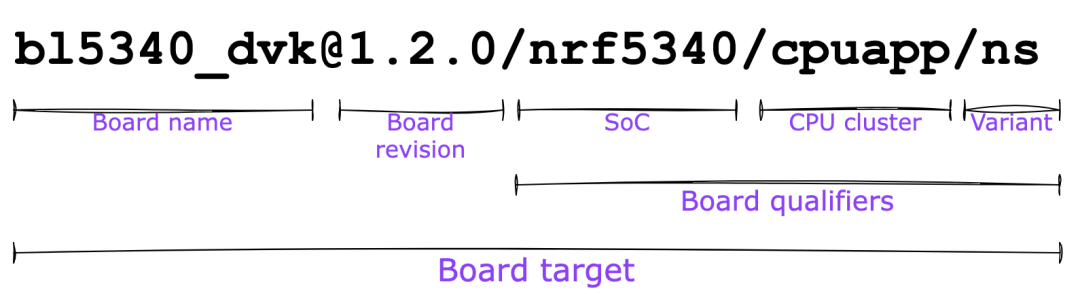
[email protected]/nrf54l15/cpuapp/ns:
nrf54l15dk
Board Name
@1.0.0
Board Version
(common in engineering sample versions)
/nrf54l15
Board qualifier for SoC
/cpuapp
Board qualifier for CPU cluster
/ns
Board qualifier for variant
Old Version Board Names
The above introduction is for Zephyr’s Hardware Model v2. There is a hierarchical relationship between the board, SoC, and CPU.
In versions of NCS v2.6.x and earlier, the board names without hierarchical relationships were used. For example:
nrf52840dk_nrf52840 and nrf52840dk_nrf52811 were considered two different boards.
Of course, you can also simply understand that the Hardware Model v2 is just replacing the underscore _ with a slash /.
3
Using Boards Variables in CMake
You may need to configure different files in CMake based on the Board.
-
${BOARDS}: Board name, e.g., nrf52840dk, nrf54l15dk
-
${BOARD_QUALIFIERS}: Suffixes, e.g., /nrf52840, /nrf54l15/cpuapp/ns
For example, in sysbuild.cmake, use different Partition Manager configuration files based on different boards:
# Multi-image partition configuration# Configure in sysbuild.cmake; the following configuration will be appended to all sub-projects' CMakeLists.txt
## Partition manager
if (EXISTS "${CMAKE_CURRENT_LIST_DIR}/configurations/${BOARD}${BOARD_QUALIFIERS}/pm_static.yml")    message(STATUS "Using Partition Manager file: ${CMAKE_CURRENT_LIST_DIR}/configurations/${BOARD}${BOARD_QUALIFIERS}/pm_static.yml")    set(PM_STATIC_YML_FILE ${CMAKE_CURRENT_LIST_DIR}/configurations/${BOARD}${BOARD_QUALIFIERS}/pm_static.yml CACHE INTERNAL "")else()    message(FATAL_ERROR "Can't find Partition Manager configurations (${CMAKE_CURRENT_LIST_DIR}/configurations/${BOARD}${BOARD_QUALIFIERS}/pm_static.yml)")endif()
Here ${BOARD}${BOARD_QUALIFIERS} is concatenated, corresponding to the configuration file directory hierarchy:
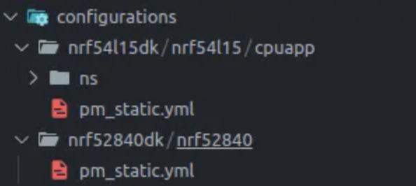
4
Custom Boards
If your project is relatively simple, you can choose not to customize a board. Directly select a Nordic development board as the base Board. Then use device tree overlay files and Kconfig configuration files to add, delete, or modify configurations.
However, defining your own board has many benefits, such as:
-
Allowing a project to support both its own Board and the development board simultaneously. During debugging, it is very useful to compare the performance of the development board with that of your own board when troubleshooting hardware issues or optimizing power consumption.
-
When developing different projects with the same board, it is very convenient to port.
-
If the chip package you choose is different from the one on the development board, and the number of pins differs, you need to customize the board.
Steps to Define a Custom Board
You can also refer to the official documentation https://docs.nordicsemi.com/bundle/ncs-latest/page/nrf/app_dev/board_support/defining_custom_board.html
Create Board
You can graphically operate in VS Code to define the board:
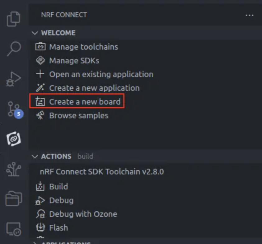
Enter the board name, which is a readable string and can contain spaces:

Enter the board name, which is the name used during compilation and cannot contain spaces:
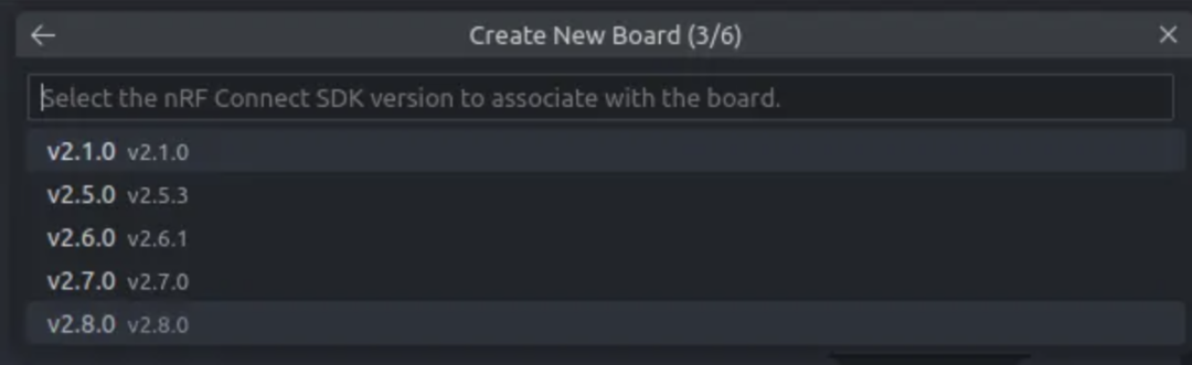
Select the NCS version to be used:
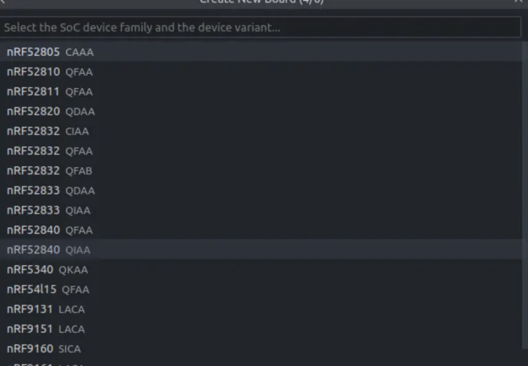
Select the location to store the boards related files:

Enter the company name as the vendor field:

After creation, it will be stored in the current project’s boards directory:
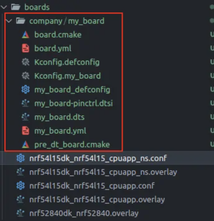
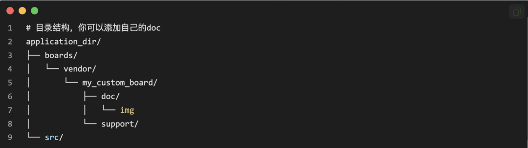
Add Default Kconfig
The default config is your <board_name>_defconfig:

You can copy the default configuration of the development board as needed, referring to ${NCS-2.8.0}/zephyr/boards/arm/nrf52840dk_nrf52840/nrf52840dk_nrf52840_defconfig
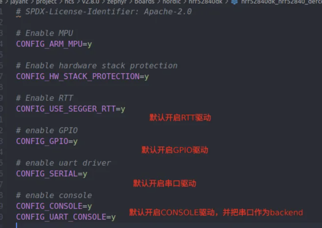
The above is to add the default configuration values. If you want to add menu options for this board, you can add your menu items in Kconfig.
It is worth mentioning that if your board does not have a 32.768kHz crystal oscillator, you need to use the internal RC oscillator. You can write the related configurations for the internal oscillator into this defconfig.
CONFIG_CLOCK_CONTROL_NRF_K32SRC_RC=y
CONFIG_CLOCK_CONTROL_NRF_K32SRC_XTAL=n
CONFIG_CLOCK_CONTROL_NRF_K32SRC_RC_CALIBRATION=y
However, if cost allows, it is still highly recommended to use an external 32k crystal oscillator. Compared to the internal RC oscillator, the external crystal has better temperature stability. In addition, the internal RC oscillator needs to be calibrated frequently with a high-frequency clock, so the power consumption will also be higher.
Add Default Device Tree Configuration
In <board_name>.dts, add your default device tree configuration. You can also copy the corresponding development board file as needed. For example:
/ ${NCS-v2.8.0}/zephyr/boards/nordic/nrf52840dk/nrf52840dk_nrf52840.dts
Here are some important ones to introduce:
Special Pin Configuration (in UICR)
When your GPIOs are insufficient, you may need to use some special pins as GPIOs. These need to write to the UICR register of the chip (similar to a Flash area that stores user configurations).
&uicr {    // bool type attribute, true if present, false if not
        // Reset pin used as reset instead of GPIO
        gpio-as-nreset;
    // Deleting the attribute means setting the bool type to false
    // NFC pins not used as GPIO
    /delete-property/ nfct-pins-as-gpios;
};
In older versions of NCS, v2.4.x and earlier, it was not set in the DeviceTree but in Kconfig:
CONFIG_GPIO_AS_PINRESET=y
CONFIG_NFCT_PINS_AS_GPIOS=n
Power Regulator Configuration
The board powers the chip externally via the VDD pin, and Nordic chips have an internal power regulator to power the core. This regulator can be configured as DC/DC or LDO. If it is DC/DC, the board needs to add corresponding inductors and capacitors.
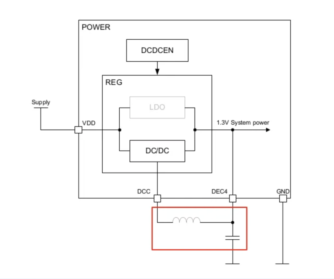
nRF52832 internal power – DC/DC mode
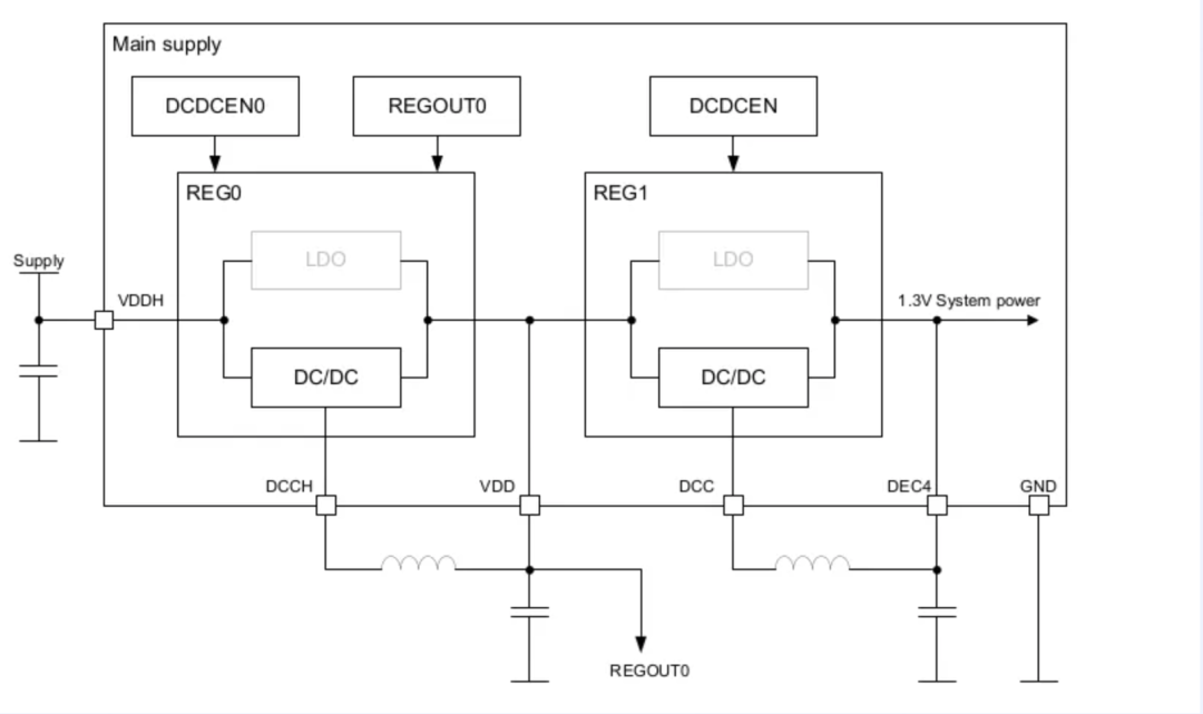
nRF52840 internal two-stage power – dual DC/DC mode
The nRF52840 has a high voltage mode, allowing a voltage input of 2.5 to 5.5V via the VDDH pin.
You can also choose not to use VDDH. Directly short VDDH and VDD, in which case Regulator0 will be skipped, and the power supply range will be 1.7~3.6V:
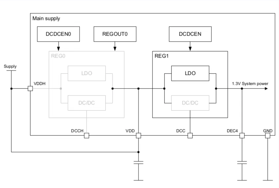
nRF52840 single-stage power – LDO mode
For most applications, single-stage power is sufficient. In addition, for packages like nRF52840-QFAA (QFN48), VDDH and VDD are internally shorted, and Regulator0 is masked. You can directly configure reg1.
// Use DC/DC
®1 { regulator-initial-mode = <NRF5X_REG_MODE_DCDC>;};// Use LDO
®1 { regulator-initial-mode = <NRF5X_REG_MODE_LDO>;};If you are using a package with VDDH power supply, use the following device tree to enable REG0’s DC/DC:
// reg0 is only defined in nrf52840-qiaa.dtsi
®0 { status = "okay";};In older versions of NCS, it was not set in the device tree but configured using Kconfig for DC/DC:
CONFIG_SOC_DCDC_NRF52X=y
CONFIG_SOC_DCDC_NRF52X_HV=y
GPIO Reserve
In the development board’s device tree, we may see some configurations under the gpio port node. We need to know what they mean.
&gpio0 { status = "okay"; gpio-reserved-ranges = <0 2>, <6 1>, <8 3>, <17 7>; gpio-line-names = "XL1", "XL2", "AREF", "A0", "A1", "RTS", "TXD", "CTS", "RXD", "NFC1", "NFC2", "BUTTON1", "BUTTON2", "LED1", "LED2", "LED3", "LED4", "QSPI CS", "RESET", "QSPI CLK", "QSPI DIO0", "QSPI DIO1", "QSPI DIO2", "QSPI DIO3","BUTTON3", "BUTTON4", "SDA", "SCL", "A2", "A3", "A4", "A5";};The gpio-reserved-ranges means: from the software level, restrict certain pins of gpio0 from being used as ordinary GPIOs because they are already connected to some components on the development board. This can prevent pin assignment issues.
<0 2> means P0.00 and the next 2 pins, which are P0.00 and P0.01, as they are used for the 32.768kHz low-frequency crystal oscillator; similarly, <17 7> means P0.17 and the next 7 pins cannot be used as ordinary GPIOs because they are the pins used by the external QSPI flash on the board, and P0.18 is the reset pin.
This only restricts the pins from being used as ordinary GPIOs; runtime errors will occur. However, it does not restrict these pins from being allocated to peripherals using pinctrl (after all, QSPI pins are allocated this way).
When copying the development board’s dts to our custom board, be careful not to copy this part entirely; it should be adjusted according to requirements.
Device Tree Nodes Dependent on Zephyr Software
There are many ready-made software modules in Zephyr that are related to hardware. For example, command line terminal shell, as well as drivers for LEDs and buttons. When you enable these software modules, they will look in the device tree for which hardware they should operate.
For example, many Zephyr Kernel functions use definitions under the /chosen node:
/{  chosen {    zephyr,console = &uart0;    zephyr,shell-uart = &uart0;    zephyr,uart-mcumgr = &uart0;    zephyr,bt-mon-uart = &uart0;    zephyr,bt-c2h-uart = &uart0;    zephyr,ieee802154 = &ieee802154;  };};
// If using OpenThread or Zigbee protocol, you need to enable 802.15.4
&ieee802154 {  status = "okay";};
Other libraries and examples use definitions under the /aliases node:
/{ aliases { led0 = &led0; led1 = &led1; led2 = &led2; led3 = &led3; pwm-led0 = & pwm_led0; sw0 = &button0; sw1 = &button1; sw2 = &button2; sw3 = &button3; bootloader-led0 = &led0; mcuboot-button0 = &button0; mcuboot-led0 = &led0; watchdog0 = &wdt0; };};Many examples will use LEDs and Buttons. When you run examples on your own board, and your board does not have definitions for LEDs or buttons, remember to delete the LED and Button related code in the examples.
The CONFIG related to LED and button in examples is:
# Remove support for LEDs and buttons on Nordic development kits
CONFIG_DK_LIBRARY=n
External Flash
The default QSPI flash on the nRF52840DK development board is:
&qspi { status = "okay"; pinctrl-0 = <&qspi_default>; pinctrl-1 = <&qspi_sleep>; pinctrl-names = "default", "sleep"; mx25r64: mx25r6435f@0 { compatible = "nordic,qspi-nor"; reg = <0>; /* MX25R64 supports only pp and pp4io */ writeoc = "pp4io"; /* MX25R64 supports all readoc options */ readoc = "read4io"; sck-frequency = <8000000>; jedec-id = [c2 28 17]; sfdp-bfp = [ e5 20 f1 ff ff ff ff 03 44 eb 08 6b 08 3b 04 bb ee ff ff ff ff ff 00 ff ff ff 00 ff 0c 20 0f 52 10 d8 00 ff 23 72 f5 00 82 ed 04 cc 44 83 68 44 30 b0 30 b0 f7 c4 d5 5c 00 be 29 ff f0 d0 ff ff ]; size = <67108864>; has-dpd; t-enter-dpd = <10000>; t-exit-dpd = <35000>; };};In the nRF7002DK, there is also an SPI Flash
&spi4 { compatible = "nordic,nrf-spim"; status = "okay"; pinctrl-0 = <&spi4_default>; pinctrl-1 = <&spi4_sleep>; pinctrl-names = "default", "sleep"; cs-gpios = <&gpio0 11 GPIO_ACTIVE_LOW>; mx25r64: mx25r6435f@0 { compatible = "jedec,spi-nor"; reg = <0>; spi-max-frequency = <33000000>; jedec-id = [c2 28 17]; sfdp-bfp = [ e5 20 f1 ff ff ff ff 03 44 eb 08 6b 08 3b 04 bb ee ff ff ff ff ff 00 ff ff ff 00 ff 0c 20 0f 52 10 d8 00 ff 23 72 f5 00 82 ed 04 cc 44 83 68 44 30 b0 30 b0 f7 c4 d5 5c 00 be 29 ff f0 d0 ff ff ]; size = <67108864>; has-dpd; t-enter-dpd = <10000>; t-exit-dpd = <5000>; };};The driver used for QSPI Flash is compatible = “nordic,qspi-nor”. The driver used for SPI Flash is compatible = “jedec,spi-nor”.
If the external flash you choose on the board is different from the one provided with the development board, you can refer to the ${NCS}/zephyr/samples/driversamples/drivers/jesd216 example. Regardless of whether you use QSPI or SPI Flash, first mount it to SPI, and then run according to the instructions of this example. The example will automatically read the Flash information and print the corresponding device tree configuration in the logs, which can be copied out. However, the Flash must support JEDEC.
JEDEC (Joint Electron Device Engineering Council) is an organization that sets standards for the semiconductor industry. For external Flash memory, JEDEC standards define the interface, performance, and functional characteristics of Flash memory. JEDEC standards ensure interoperability and compatibility of Flash memory produced by different manufacturers.
Partition Manager
When upgrading with MCUBoot, if you need to place the Second slot in external Flash, you need to add the following configuration to let the Partition Manager know that external Flash should also participate in memory partitioning:
chosen { nordic,pm-ext-flash = &mx25r64; // Assign to the label of your external flash};Compiling with Custom Boards
In the VS Code Build interface, you can select the custom Board:
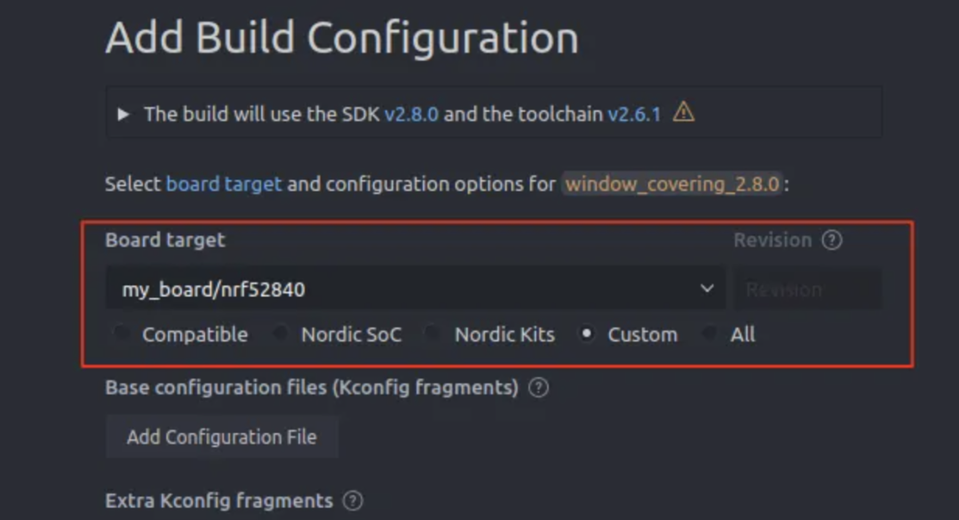
You can also compile from the command line using the current board as a parameter:
west build -d build -b my_board/nrf52840 --sysbuildCompilation Process and Output Files
1
Compilation Process
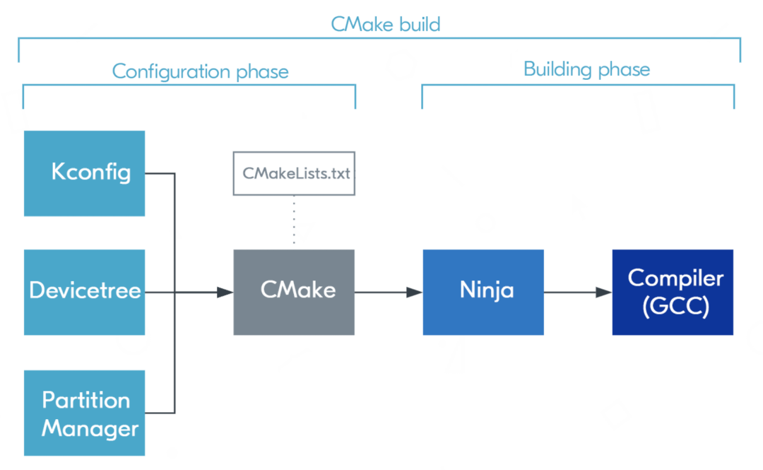
2
Output Files
The following paths are based on enabling sysbuild:
-
Current application firmware: build/<your_application_name>/zephyr/zephyr.hex
-
Current multi-project compiled merged firmware: build/merged.hex; if there are multiple cores, each core will have its own merged_<core>.hex
-
DFU upgrade files: build/dfu_application.zip, used for upgrade packages during upgrades via Bluetooth, etc.
For more output files, please refer to the official documentation.
https://docs.nordicsemi.com/bundle/ncs-latest/page/nrf/app_dev/config_and_build/output_build_files.html
3
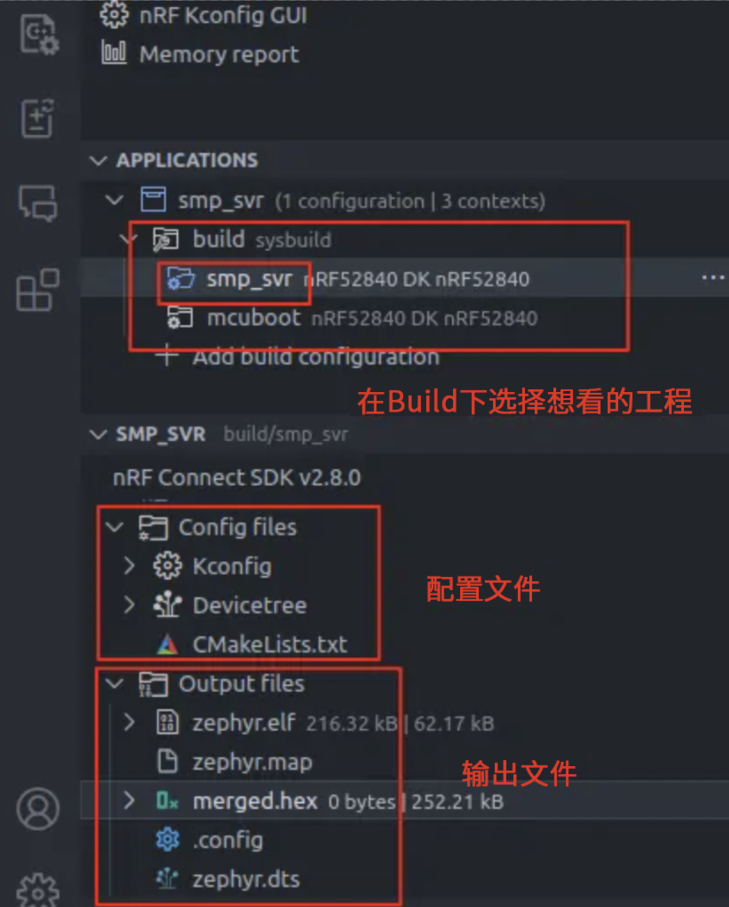
VS Code Interface
You can also view all source codes, configuration files, and output files involved in the compilation in the nRF Connect for VS Code plugin interface:

[Contact Us]
Chinese Official Website: www.nordicsemi.cn
English Official Website: www.nordicsemi.com
WeChat Official Account: nordicsemi
[Nordic Developer Forum]
https://devzone.nordicsemi.com
[Sales Contact]
Beijing Branch: +86 010 8438 2767
Shanghai Branch: +86 21 6330 0620
Shenzhen Branch: +86 755 8322 0147


Click “Read the Original” to Explore More Nordic Information