
In the previous article (Getting Started with Zephyr: Kconfig), we learned how to use the “Kconfig” infrastructure to enable and disable specific Zephyr subsystems. Specifically, we observed the three main elements of the Kconfig infrastructure. First, we understood how the Kconfig infrastructure is formulated and provided an example of a Kconfig file that enables the LED subsystem. Second, we learned how to enable or disable specific Zephyr subsystems through the graphical user interface of Kconfig when using Nordic VS Code extensions. Finally, we also learned about a mechanism for customizing Zephyr that can be incorporated into CI/CD-based systems.
In addition to customizing the RTOS to enable or disable specific subsystems, a standard step in developing embedded software is to add support for communication buses and peripherals. As mentioned in the previous blog post, other MCU vendors have included customization features in their integrated development environments, including enabling communication buses and setting their parameters. On the other hand, Zephyr borrows from another structure from the Linux kernel (remember, Kconfig also originates from the Linux kernel), which is the “Devicetree”. Devicetree, abbreviated as DT, is a data structure with its own hardware description language. As ARM-based systems on chips (SoCs) and system on modules (SoMs) running embedded Linux have become popular, Devicetrees have started to gain traction in embedded software. Linux was originally developed on Intel-based CPUs, where the bus design used supported automatic detection of hardware connected to the CPU. Therefore, there was no need to describe the hardware in advance. However, when ARM entered the market, new communication protocols and buses were introduced that lacked any detection mechanism. Consequently, the Linux kernel needed a tool to identify these buses and connected devices. It is important to note that while Zephyr borrows the concept of devicetree from the Linux kernel, there are still sufficient nuances in how Zephyr employs devicetrees.
Basic Syntax
For embedded software engineers without a Linux background, the devicetree can often be anxiety-inducing, but the most important point about the devicetree is that it is neither magical nor mysterious. It is simply a loosely structured file. The file consists of nodes, each containing a specific set of definitions. A node can reference other nodes or contain other nodes. For example, the following code snippet describes the LEDs on the Nordic nRF52840 development kit:
(https://www.nordicsemi.com/Products/Development-hardware/nrf52840-dk)
leds { compatible = "gpio-leds"; led0: led_0 { gpios = <&gpio0 13 GPIO_ACTIVE_LOW>; label = "Green LED 0"; }; led1: led_1 { gpios = <&gpio0 14 GPIO_ACTIVE_LOW>; label = "Green LED 1"; }; led2: led_2 { gpios = <&gpio0 15 GPIO_ACTIVE_LOW>; label = "Green LED 2"; }; led3: led_3 { gpios = <&gpio0 16 GPIO_ACTIVE_LOW>; label = "Green LED 3"; };};The “leds” node describes the four LEDs on the development kit.
By the way, if you have a Linux background, you will notice the “compatible” property in the above example. You might immediately conclude (as I did initially) that Zephyr will “find” device drivers with corresponding “compatible” values and call the functions specified in the device driver to control the GPIO. This is incorrect! Zephyr has its own mechanism to associate entries in the device tree with source code, which is called “bindings”, and we will elaborate on this in the next article. For now, we must remember that Zephyr’s use of devicetrees is entirely different from Linux.
Returning to this example, the four LEDs referenced in the “leds” node also reference the node itself! For instance, in the following line, the “led0” node specifies the GPIO used to control a specific LED:
led0: led_0 { gpios = <&gpio0 13 GPIO_ACTIVE_LOW>; label = "Green LED 0";}In the example above, GPIO0_13 controls LED0 on the board, which is an active-low GPIO. The node consists of the following elements:
-
“led0” is the “node label”, used to reference the Devicetree node.
-
“led_0” is the node’s “full name”. Typically, a node’s full name consists of the node name and unit address (e.g., “my-node@12345678”), but nodes without addresses are also acceptable (sometimes having an address does not make sense, and this is one of those cases).
-
“gpios” is an example of a “property” of the “led0” node. The property is ultimately used by the source code to control the hardware in some way. In this example, the “gpios” property defines the GPIO port, pin, and active state. Device drivers use this information to control the GPIO.
-
“label” is also a property of the “led0” node. Specifically, the label property can retrieve a more descriptive name for the node. In this example, “Green LED 0” can be used instead of referencing the node as “led0”.
Location and Hierarchy of Devicetree
In the previous section, we saw an example of the devicetree node for LEDs on the Nordic nRF52840 development kit. Browsing through different devicetrees in the Zephyr repository may be helpful (we will discuss why in future blog posts). Devicetrees are located in two central locations within the Zephyr repository. The devicetrees for the many supported boards in Zephyr are located in the “boards” directory under the respective processor architecture directory. For example, the top-level devicetree for the nRF52840 development kit is located in the “boards/arm/nrf52840dk_nrf52840” directory:
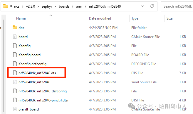
In the “top-level” devicetree file, the extension is always “.dts”, while the intermediate devicetree files referenced by the top-level devicetree have the extension “.dtsi”. Intermediate devicetree files can contain other intermediate devicetree files. In the example above, if we open the top-level devicetree file “nrf52840dk_nrf52840.dts”, we will see nodes corresponding to the LEDs on the board!
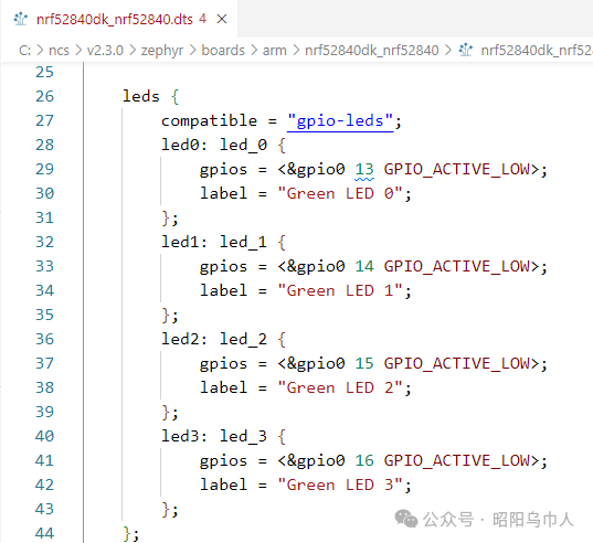
If we scroll to the top of that file, we will see the following statements:
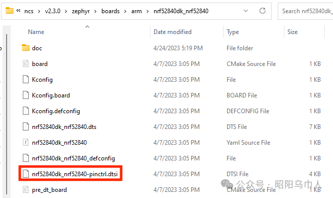
/dts-v1/;#include #include "nrf52840dk_nrf52840-pinctrl.dtsi"The first line indicates the version of the devicetree model for the parser. The second and third lines include intermediate devicetree files. If you are familiar with C (and C++) programming, you will find that its format is similar to including header files, using the “#include” preprocessor macro. The second include file “nrf52840dk_nrf52840-pinctrl.dtsi” is located in the same directory as the top-level directory:
The first include file is a variant of the nRF52840 SoC itself, located in the Zephyr repository under the dts/arm/nordic directory:
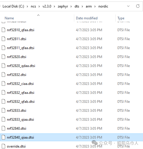
If we open “nrf52840_qiaa.dtsi”, we will find that there is not much content inside:
#include #include flash0 { reg = <0x00000000 DT_SIZE_K(1024)>;}sram0 { reg = <0x20000000 DT_SIZE_K(256)>;}/ { soc { compatible = "nordic,nRF52840-QIAA", "nordic,nRF52840", "nordic,nRF52", "simple-bus"; };};For the most part, it simply references the intermediate devicetree file “nrf52840.dtsi” located in the same directory. If we open “nrf52840.dtsi”, we will find that it describes the Nordic nRF52840 SoC in detail:
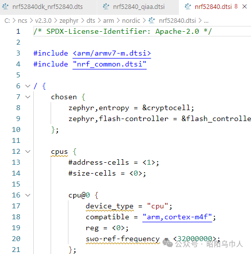
As we saw above, the file describes the details of the CPU within the SoC, indicating that it is an ARM Cortex-M4 running at a frequency of 32MHz, which matches the SoC’s datasheet!
Using Devicetree in Source Code
Now that we have understood the structure of the devicetree and its hierarchy in describing hardware, we can look at how to use it in source code. Let’s select the relevant parts of the “blinky” example in Zephyr (found in the samples/basic/blink/src directory):
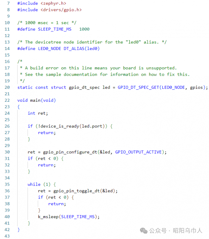
Line 14 extracts the “led0” node from the device tree. Line 20 retrieves the “gpios” property of the “led0” node from the device tree and stores it in a data structure. Then, the “led” data structure will be used in the rest of the main function to control the GPIO. First, in line 26, we check if the specified GPIO port is ready. If so, in line 30, we configure the GPIO pin as output. Finally, we toggle the GPIO pin in line 36 of the main while loop. We can see that the GPIO functions used above all have the suffix “_dt”. This is because the parameters for these functions are data structures obtained from the devicetree, so the corresponding functions must be called.
Conclusion
In this article, we learned how to use “Devicetree” to add support for customized hardware in Zephyr-based firmware. Through a “blinky” example, we learned how to describe the LEDs on the board and specify the corresponding GPIO. We also learned where to find devicetree files in the Zephyr repository and how to start describing the board from the CPU itself. One of the biggest advantages of using devicetree files in Zephyr, compared to other mechanisms provided by MCU vendors in integrated development environments, is that we can leverage the device drivers written by others. Typically, in different MCU-specific environments and integrated development environments, we need to call libraries or write driver code from scratch. In contrast, with Zephyr’s use of devicetrees and device driver models, we can take advantage of the work done by others. We can focus on writing the business logic of the final application. In the next article, we will unveil the mysteries of Zephyr, exploring how it uses devicetrees and how it differs from the Linux kernel.