The power system is a real-time balancing system where generation, transmission, and consumption must occur instantaneously. Any delay or interruption in communication can lead to equipment damage, widespread power outages, or even grid collapse. Therefore, protocols specifically designed for the power industry environment must be used.
Power-specific protocols can be categorized into the following major types based on their application systems and scenarios:
1. Substation Automation System Protocols (Protection and Control)
This is the core area of power-specific protocols, with the highest requirements.
-
IEC 60870-5-101 / 104 (commonly referred to as 101/104 protocols)
-
101 Protocol: Uses serial communication (such as RS-232/485), with a slower transmission rate, commonly used in early systems or scenarios with limited channel conditions.
-
104 Protocol: This is the networked version of the 101 protocol, using TCP/IP networks, and has become the mainstream today. It transmits the application layer data units of the 101 protocol through TCP ports, greatly improving transmission efficiency and convenience.
-
Application Scenario: Mainly used for communication between the dispatch master station and substations/power plants, it is one of the most widely used protocols in China’s power dispatch data network.
-
Functions: Remote control (remote control of circuit breakers/switches), remote adjustment (adjusting device parameters), remote signaling (collecting switch status, alarm information), remote measurement (collecting voltage, current, power, and other analog quantities).
-
IEC 61850
-
Application Scenario: The core protocol for digital substations and smart grids, representing the current and future direction of technological development.
-
“Interoperability”: The core idea. Intelligent electronic devices (IEDs) from different manufacturers can seamlessly collaborate within the same system, solving the “island” problem of incompatible protocols in traditional substations.
-
Object-Oriented Modeling: Abstracts physical devices in substations (such as circuit breakers, transformers) into logical devices and service models, making configuration and maintenance more intuitive.
-
MMS (Manufacturing Message Specification): Used for transmitting slow data in a client-server model (such as configuration, settings, alarms).
-
GOOSE (Generic Object-Oriented Substation Event): Used for fast and reliable transmission of status quantities and trip commands between IEDs within the station. It communicates directly between IEDs via switches without going through the master station, achieving extremely fast speeds (in milliseconds), replacing traditional hard wiring.
-
SV (Sampled Values): Used for transmitting instantaneous values of current/voltage collected by merging units (MUs) for use by protection and control devices.
-
Importance: IEC 61850 is not just a protocol but a complete communication system, serving as the foundation for achieving substation intelligence.
2. Distribution Automation System Protocols
-
DNP3 (Distributed Network Protocol)
-
Designed for harsh industrial environments, it features robust data integrity checks and error recovery mechanisms.
-
Supports master-slave, multi-master, and peer-to-peer communication.
-
Flexible reporting mechanism, supporting polling and active reporting (timestamped reports).
-
Application Scenario: Widely used in North America, and in China, it is commonly used in distribution automation and renewable energy (wind farms, photovoltaic power plants) monitoring and other fields.
-
Comparison with 104 Protocol: Similar functions, both are backbone protocols for SCADA systems, but differ in message structure, application fields, and historical origins.
3. Smart Meter and Electricity Information Collection System Protocols
-
DL/T 645 Protocol
-
The physical layer typically uses RS-485 bus, allowing one concentrator to connect multiple meters.
-
Defines the frame format and read/write rules for meter data, such as reading current electricity, voltage, current, historical frozen data, etc.
-
There are two versions, 1997 and 2007, with the new version being more powerful.
-
Application Scenario: A mandatory standard for communication between residential and commercial smart meters and concentrators, collection terminals in China.
A summary of power industry standard protocols is as follows:

IEC61850 standard is the only international standard for substation automation systems based on a universal network communication platform, which references and absorbs many existing related standards, including mainly:IEC870-5-101 remote communication protocol standard;IEC870-5-103 relay protection information interface standard;UCA2.0 (Utility Communication Architecture 2.0) (communication protocol system for substations and feeder devices developed by the American Electric Power Research Institute); ISO/IEC9506 manufacturer information specification;MMS (Manufacturing Message Specification).IEC61850 corresponds to the Chinese power industry standard numberDL/T860.
IEC60870-5 series protocols are related to the standardized transmission of information for power dispatch automation systems, includingIEC60870-5-101 (basic remote communication protocol meeting dispatch requirements),IEC60870-5-102 (communication protocol for electric energy transmission),IEC60870-5-103 (protocol for data communication transmission between relay protection and interval layer (IED) devices and station control layer devices),IEC60870-5-04 (remote protocol for network transmission).
IEC60870-6 series standards “Remote devices and systems Part 6: Remote communication protocols compatible with ISO standards and ITU-T recommendations” includes two subsets of protocols: TASE.1 and TASE.2. To align with international standards, China has chosen to adopt the TASE.2 protocol subset to gradually upgrade the application of the power industry standard DL/T476-1992 “Real-time data communication application layer protocol for power systems”.
DNP3DNP (Distributed Network Protocol, is a communication protocol used between automation components, commonly found in industries such as power and water treatment.DNP3.0 is the American national standard developed by the IEEE Power Engineering Society (PES) based on IEC, and is an international standard protocol.
Here, we will focus on understanding the IEC104 and IEC61850 protocols.
IEC104 Protocol Analysis
The IEC104 protocol, also known as the IEC104 specification, is an international standard widely used in the power and urban rail transit industries. The IEC104 specification originates from IEC 60870-5-104 (commonly referred to as the 104 protocol), which is an international standard communication protocol for power automation systems. It is part of the IEC 60870-5 series of standards, specifically defining the specifications for transmission over TCP/IP networks.
The IEC104 protocol serves as the backbone protocol for data communication between the dispatch master station (control center) and remote terminal units (RTUs) or intelligent electronic devices (IEDs) in substations or power plants.
The 104 protocol can be understood as the “networked upgrade” of the IEC 60870-5-101 (101 protocol, which uses serial links). It encapsulates and transmits the application service data units (ASDUs) of the 101 protocol using the TCP/IP protocol, thereby fully utilizing the high speed, wide coverage, and easy connectivity of Ethernet.
The IEC104 protocol implements the “four remote” functions of the power system, which are core to the SCADA (Supervisory Control and Data Acquisition) system. The “four remote” functions are:
-
Remote Signaling (Digital Input DI):
-
Function: Collects the switch status signals and alarm signals from the remote station.
-
Data Example: The “open/close” status of circuit breakers (switches), relay protection action signals, grounding knife position, total alarm signals, etc.
-
Characteristics: These are digital quantities/status quantities, typically represented by a single binary digit (0 or 1).
Remote Measurement (Analog Input AI):
-
Function: Collects the analog measurement values from the remote station.
-
Data Example: Active power, reactive power, current, voltage, frequency, transformer oil temperature, etc.
-
Characteristics: These are continuously varying analog quantities, which are converted to digital values during transmission, along with dimensions and scales.
Remote Control (Digital Output DO):
-
Function: Sends switch operation commands from the master station to the remote station, changing the operating state of the device.
-
Operation Example: Remote control of circuit breakers to “close” or “open”.
-
Characteristics: This is an output command, with extremely high safety requirements. A strict process of “select-execute-return” is usually adopted to ensure the operation is correct.
Remote Adjustment (Analog Output AO):
-
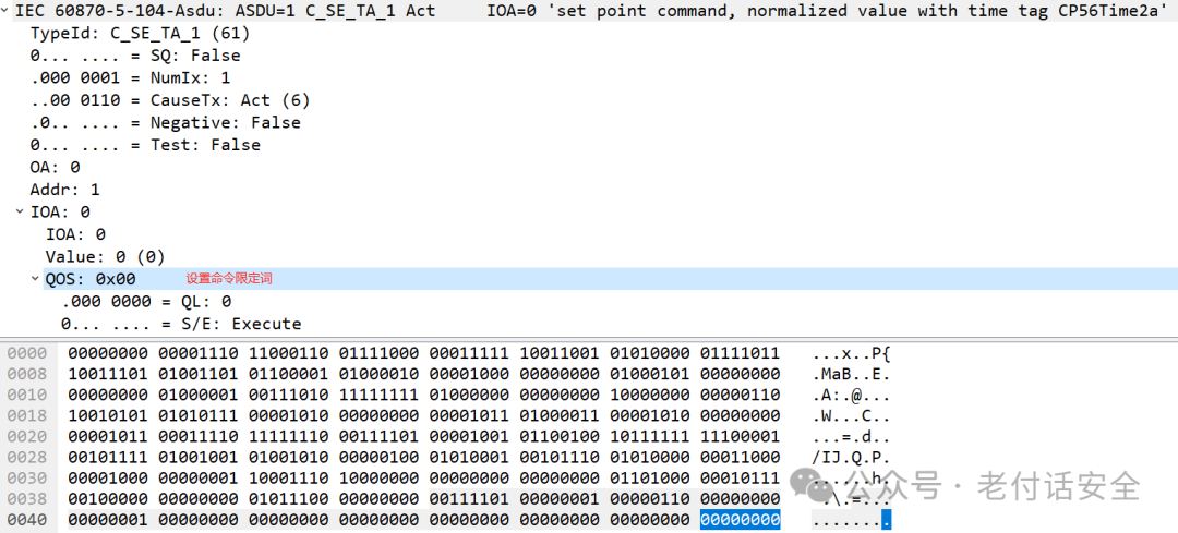
Function: Sends set values or adjustment commands from the master station to the remote station, adjusting the operating parameters of the device.
-
Operation Example: Adjusting the active power output set value of a generator, adjusting the tap position of a transformer, etc.
-
Characteristics: Similar to remote control, but the objects of operation are analog parameters.
The communication architecture of the 104 protocol is a typical Client/Server (C/S) model:
-
Server Side: Substation/Power Plant.
-
Typically consists of an RTU, a comprehensive automation system, or a dedicated communication gateway acting as the server.
-
It is responsible for collecting the “four remote” data from all intelligent devices (IEDs) within the station and storing it in a real-time database.
-
It listens on a fixed TCP port (2404 is the default port for the 104 protocol).
-
Client: Master Station/Dispatch Center/Control Center.
-
Typically consists of the front-end processor or communication processor of the SCADA system acting as the client.
-
It actively initiates a TCP connection to the substation server.
-
It is responsible for initiating total calls, clock synchronization, remote control commands, and receiving and processing all data uploaded from the substation.
The structure of the IEC104 protocol
The messages of the 104 protocol are carried in TCP/IP data packets
- Application Layer Protocol: Defines the format and transmission method of application data.
- Transport Layer Protocol: Utilizes the TCP/IP protocol stack to achieve reliable data transmission.
In the 104 protocol, APDU is a core concept. APDU (Application Protocol Data Unit) is the basic unit used for data transmission between remote terminal devices (RTUs) in power systems and industrial automation systems and the control center (SCADA system).
APDU consists of two parts:
-
APCI (Application Protocol Control Information)
-
ASDU (Application Service Data Unit)
-
The structure and function of APDU ensure the reliability and effectiveness of data transmission.
APDU: Application Protocol Data Unit APCI: Application Protocol Control Information ASDU: Application Service Data Unit
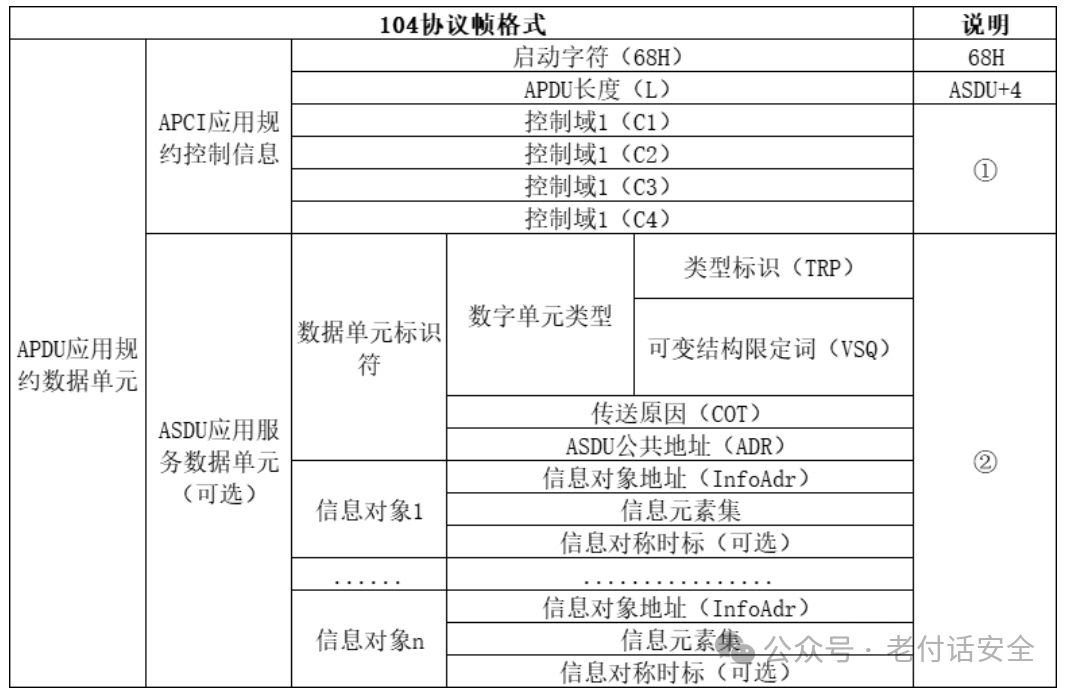
The protocol format of the 104 protocol is as follows:
-
APCI – Application Protocol Control Information
-
Start Byte: Fixed to 0x68.
-
APDU Length: Indicates the length of the entire APDU (ASDU + Control Field) that follows.
-
Control Field: This is the soul of the 104 protocol, consisting of 4 bytes. It defines the type and sequence number of the message, mainly divided into:
-
I Format Frame: Used for transmitting actual data (such as remote measurement, remote signaling, remote control confirmation, etc.). Contains the sending sequence number
<span>N(S)</span>and the receiving sequence number<span>N(R)</span>, used for the confirmation retransmission mechanism over TCP, ensuring reliable and ordered data transmission. -
S Format Frame: Confirmation frame. When the receiver receives a batch of I format frames, if there is no data to send, it sends an S format frame to confirm the received data, preventing the sender from timing out and retransmitting.
-
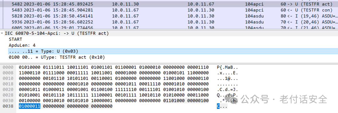
U Format Frame: Control frame. Used to establish and release connections, including STARTDT (Start Data Transmission), STOPDT (Stop Data Transmission), and TESTFR (Test Frame).
-
This is the transmission frame header of the 104 protocol, used to control the transmission of messages.
-
Fixed length of 6 bytes.
-
Contains three key parts:
ASDU – Application Service Data Unit
-
This is the main body of the data content, containing specific “four remote” information.
-
Its structure is complex, containing multiple fields:
-
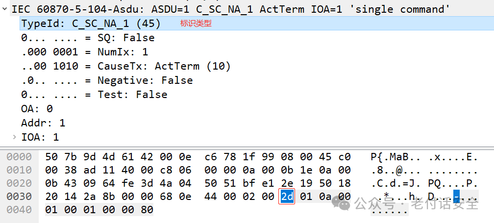
Type Identifier: Indicates the type of ASDU, such as
<span><span>M_SP_NA_1</span></span>(single-point remote signaling),<span><span>M_ME_TE_1</span></span>(timestamped remote measurement), etc. -
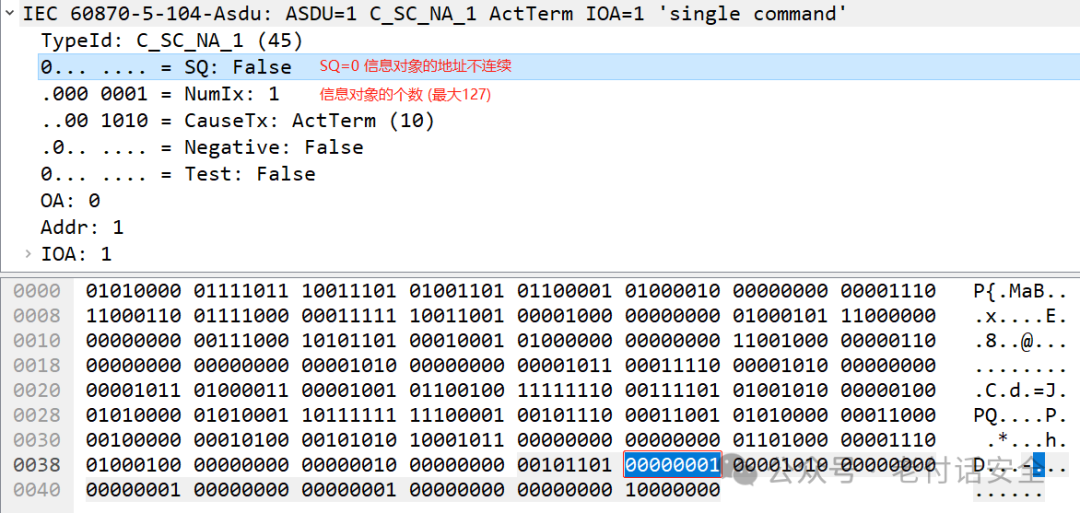
Variable Structure Qualifier: Indicates the number and arrangement of information objects (whether sequential or independent).
-
Reason for Transmission: Explains the reason for data upload, such as
<span><span>periodic/cyclic</span></span>,<span><span>burst</span></span>,<span><span>total call</span></span>,<span><span>remote control selection</span></span>,<span><span>remote control execution</span></span>, etc. This field is crucial for understanding the data interaction process. -
Common Address: Usually refers to the station address, used to distinguish different substations (RTUs) on the same communication link.
-
Information Object Address: The unique address of a specific remote signaling point or remote measurement point, such as “Switch 101 of Line 1”.
-
Information Element: The data value itself, such as whether the switch status is “closed (1)” or “open (0)”, or the current value is “520.1A”.
-
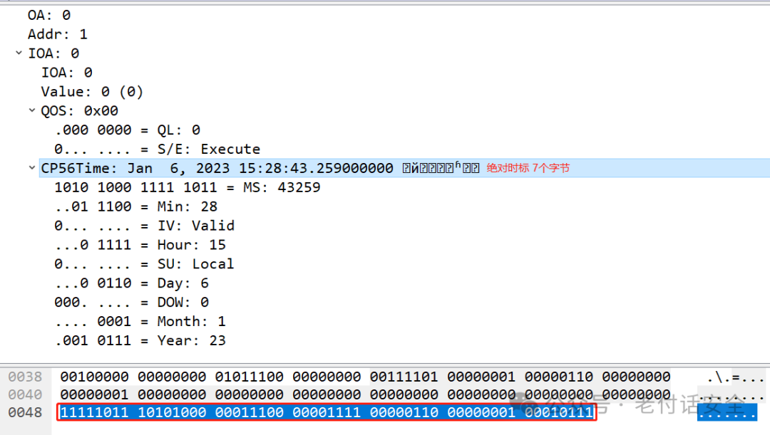
Timestamp: An optional field that provides an accurate timestamp (millisecond level) for the data.
Data Interaction Process
A typical communication session process for the 104 protocol is as follows:
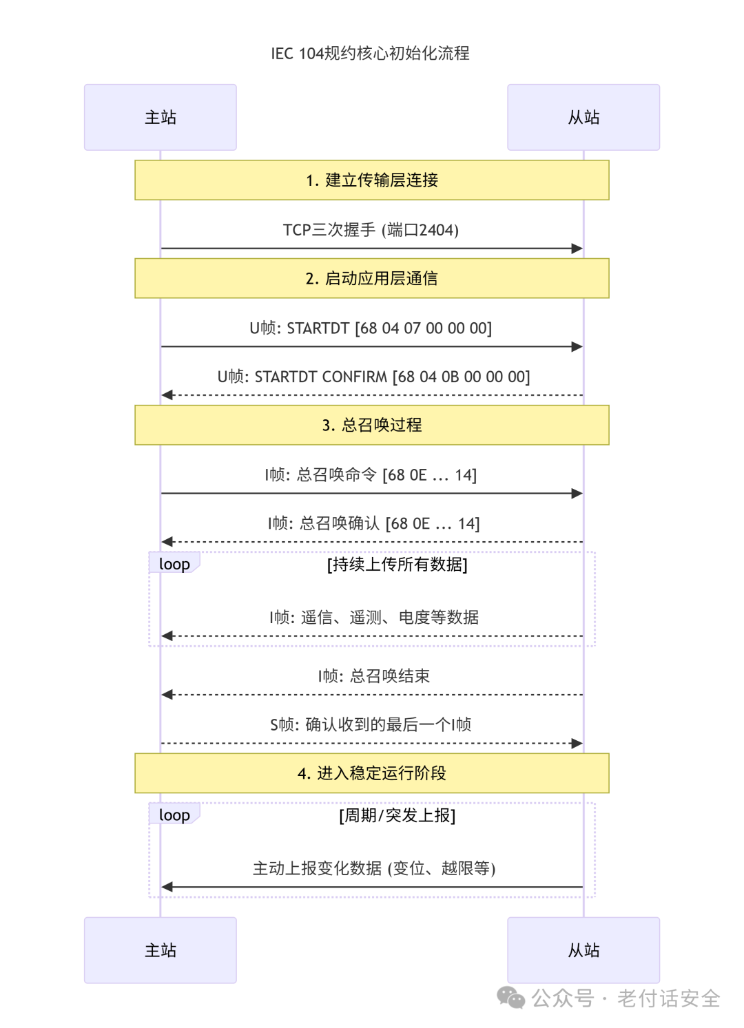
Step 1: Establish TCP Connection
-
Process: The master station (client) actively initiates a TCP three-way handshake with the slave station (server, default port 2404) to establish a reliable network connection.
-
Essence: This only establishes the underlying data channel; communication at the application layer (104 protocol) has not yet begun.
Step 2: Start Data Transmission (U Frame Exchange)
This is the “switch” for application layer communication of the 104 protocol.
-
The master station sends a start frame:
<span>68 04 07 00 00 00</span> -
Convert to binary:
<span>0000 0111</span> -
According to the U format frame definition:
-
Meaning: The master station tells the slave station: “Our TCP connection has been established, now please start sending me data.”
-
BIT 1:
<span>1</span>indicates this is a STARTDT (Start Data Transmission) command. -
BIT 2:
<span>1</span>indicates this is an ACTIVATE request. -
Other bits are all 0.
-
<span>68</span>: The start character of the 104 protocol, fixed to 0x68. -
<span>04</span>: Indicates the length of the subsequent APDU (excluding the start character itself) is 4 bytes. Here, it is the 4 bytes of the control field. -
<span>07 00 00 00</span>: This is the 4-byte control field used for the U format frame. -
The slave station sends a start confirmation frame:
<span>68 04 0B 00 00 00</span> -
Convert to binary:
<span>0000 1011</span> -
According to the U format frame definition:
-
Meaning: The slave station replies to the master station: “I received your start request, and I agree to start data transmission.”
-
BIT 1:
<span>1</span>indicates this is a STARTDT command. -
BIT 2:
<span>0</span>(note the difference here) -
BIT 3:
<span>1</span>indicates this is a CONFIRM (confirmation) response. -
<span>68 04</span>: Same as above, start character and length indication. -
<span>0B 00 00 00</span>: Control field. -
Thus, the application layer communication of the 104 protocol officially starts.
Step 3: Total Call Process (I Frame Exchange)
The purpose of the total call is to allow the master station to obtain all current static data from the slave station, completing the initialization of the data mirror.
-
The master station sends a total call command:
<span>68 0E 00 00 00 00 64 01 06 00 01 00 00 00 00 14</span> -
<span>64</span>: Type Identifier. Decimal 100. In the 104 protocol,<span>64</span>(0x64) corresponds to<span>C_IC_NA_1</span>, meaning “total call command”. -
<span>01</span>: Variable Structure Qualifier. The highest bit is 0, indicating the information object is sequential; the lower 7 bits are 1, indicating this ASDU contains 1 information object. -
<span>06 00</span>: Reason for Transmission. 0x0006, broken down as follows: -
<span>01 00</span>: Common Address. 0x0001, indicating the station address is 1. Used to distinguish different slave stations. -
<span>00 00 00</span>: Information Object Address. The total call is a global operation, with no specific point address, so this is fixed at 0. -
<span>14</span>: Qualifier QOI. 0x14 (decimal 20), this is a specific value indicating “total call (global)”. -
The low byte
<span>06</span>indicates “activation”, which is the start of a command. -
The high byte
<span>00</span>usually indicates unused or P/N bit is 0 (definite confirmation). -
<span>68</span>: Start character. -
<span>0E</span>: APDU length, indicating there are 14 bytes following. -
<span>00 00</span>: Sending sequence number<span>N(S)</span>= 0. (First I frame) -
<span>00 00</span>: Receiving sequence number<span>N(R)</span>= 0. -
APCI Part (Message Header)
-
ASDU Part (Data Unit)
-
Meaning: The master station tells the slave station: “(Type = total call command), I have 1 information object (variable structure qualifier), this is an activation command (reason for transmission), sent to station 1 (common address), requesting a global total call (QOI=20).”
-
The slave station sends a total call confirmation:
<span>68 0E 00 00 02 00 64 01 07 00 01 00 00 00 00 14</span> -
Most of it is the same as the master station command, the key difference is:
-
<span>07 00</span>: Reason for Transmission. 0x0007, indicating “activation confirmation”. The slave station uses this to confirm it has received the activation command and started execution. -
<span>00 00</span>: Sending sequence number<span>N(S)</span>= 0. (First I frame sent by the slave station) -
<span>02 00</span>: Receiving sequence number<span>N(R)</span>= 2. This value is very important! It tells the master station: “I have correctly received all I frames sent by you with sequence numbers less than 2 (i.e., your frame 0 and frame 1), please start sending from sequence number 2 next time.” -
APCI Part
-
ASDU Part
-
Meaning: The slave station replies to the master station: “I confirm that I have received your total call activation command and have started processing it.”
Step 4: Slave Station Uploads Data and Ends Call
-
The slave station uploads I frame information frames
-
<span>M_SP_NA_1</span>(single-point remote signaling) -
<span>M_ME_TE_1</span>(timestamped remote measurement) -
Process: The slave station begins to package all remote signaling (switch status), remote measurement (measurement values), and electric quantity (accumulated values) data in memory into multiple I format frames, sending them sequentially to the master station.
-
Characteristics: The type identifiers, information object addresses, and information elements of these messages may vary, representing different data points. For example:
-
Each time an I frame is sent, the sending sequence number of the slave station
<span>N(S)</span>increases by 1. -
The slave station sends a total call end frame
-
Type Identifier: Still
<span>C_IC_NA_1</span>(0x64). -
Reason for Transmission: Changes to
<span>0x000A</span>, indicating “activation termination”. -
Once all static data has been uploaded, the slave station will send a special I frame to mark the end of the total call process.
-
This frame’s ASDU is similar to the total call command:
-
Meaning: “I have sent all the initial data you requested, and the total call process is now officially over.”
-
The master station replies with an S confirmation frame
-
After receiving the total call end frame, the master station will reply with an S format frame.
-
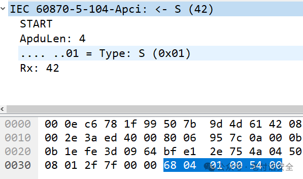
The S format frame is very simple, for example:
<span>68 04 01 00 [N(R) L] [N(R) H]</span>. -
Where
<span>N(R)</span>will equal the<span>N(S) + 1</span>of the last I frame sent by the slave station. -
Meaning: “I confirm that I have received all I frames with sequence numbers before
<span>N(R)</span>.”
Step 5: Enter Stable Operating Cycle
-
After the total call is completed, the system initialization ends, and it enters a stable operating state.
-
“Wherever data changes, the slave needs to actively report”: This is the core of the 104 protocol—burst transmission.
-
During the stable operating period, the master station no longer needs to keep polling. As long as any data point from the slave (such as switch status, measurement values) changes, or an event occurs, the slave will immediately actively organize an I frame and send it to the master station.
-
This mechanism greatly improves real-time performance and reduces waste of network bandwidth.
-
The master station will also periodically perform clock synchronization and may initiate electric quantity freezing and other periodic operations.
-
Both parties will use TESTFR (test frame) to maintain the heartbeat of the connection.
This complete process ensures that the master station can obtain a complete and accurate data mirror from the slave station, laying a solid foundation for subsequent efficient and real-time monitoring and control.
Actual Packet Analysis
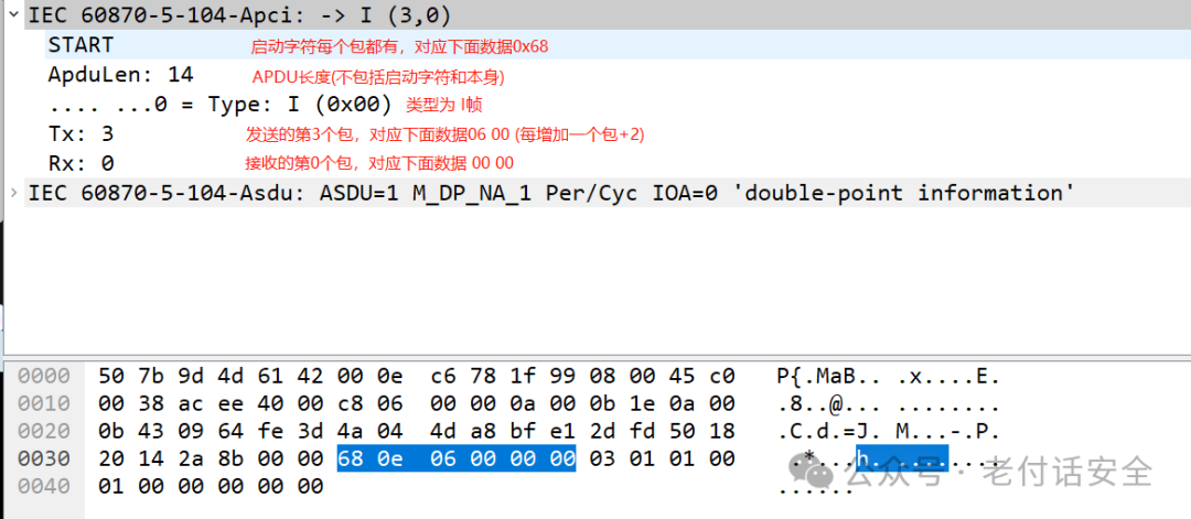
I Frame Message:
S Frame Message:
U Frame Message:
ASDU Service Data Unit: TypeId
ASDU Service Data Unit: Variable Structure Qualifier
ASDU Service Data Unit: Reason for Transmission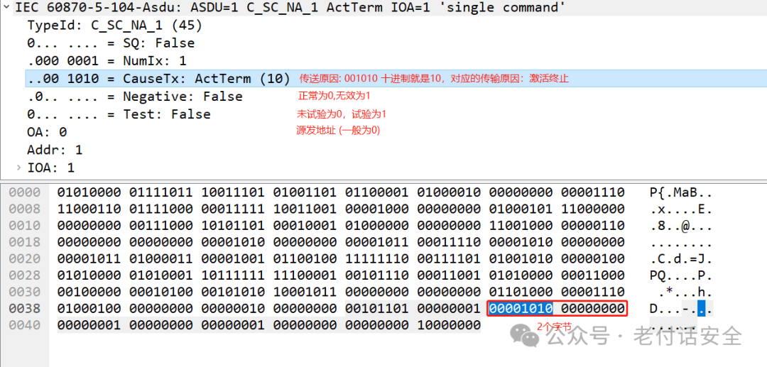
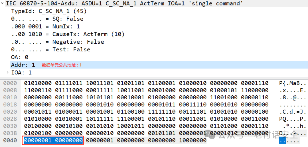
ASDU Service Data Unit: Application Service Data Unit Common Address
ASDU Service Data Unit: Absolute Timestamp
ASDU Service Data Unit: Set Value (Remote Measurement)

End
