In pipeline production scenarios, precise control based on product quantity is key to achieving automated warnings and batch management. For example, triggering a buzzer alarm when production reaches a specified quantity alerts operators to perform subsequent actions such as material change and quality inspection. The counter function of Mitsubishi PLC can efficiently meet such requirements by flexibly configuring the “current value” (real-time counting result) and “set value” (target counting threshold). This article takes the “pipeline product counting alarm” as an example and details three different counter application schemes, covering core techniques such as flag control and dynamic adjustment of set values.
1. Control Requirements and Scenario Analysis
The control object is an automated pipeline, with the core requirement being to trigger a buzzer alarm based on a preset quantity. The specific scenarios and action requirements are as follows:
-
Signal Input: Each time a product is produced, a sensor triggers a PLC input point X0 (counting trigger signal); three mode selection buttons X1, X2, and X3 are set, corresponding to different alarm counting thresholds.
-
Function Logic: Pressing X1 (Mode 1) triggers the buzzer (controlled by Y0) when the product count reaches 10,000; pressing X2 (Mode 2) triggers the alarm at 20,000; pressing X3 (Mode 3) triggers the alarm at 30,000.
-
Reset Requirements: After the alarm is triggered, the counter must be reset through the mode buttons to stop the alarm and restart counting.
Figure 1 is a schematic diagram of the device, clearly presenting the interaction between the sensor, control buttons, and buzzer, providing a hardware logic basis for subsequent program design.
Figure 1 Device Schematic
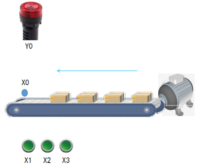
(This is the position of the device schematic mentioned in the original text; in actual applications, it should be paired with the on-site equipment layout diagram.)
2. Three Implementation Schemes: From Basic to Advanced Counter Applications
Based on the above requirements, three different implementation schemes can be designed by combining the “current value comparison” and “set value configuration” features of the Mitsubishi PLC counter, each suitable for different levels of on-site complexity and expansion needs.
Scheme 1: Flag + Multiple Counters – A Basic and Reliable Mode Switching
This scheme achieves multi-threshold counting control through the logic of “mode button triggering flags, with flags controlling different counters”. The core is to use intermediate relays (M points) as mode flags, paired with multiple counters corresponding to different set values.
1.1 Mode Selection Logic: Triggering and Resetting Flags M0-M2
The core of mode selection is to control the combination bit component K1M0 through the MOV instruction, allowing for individual conduction of different mode flags (interlocking), while resetting the counters to ensure counting starts from zero. The specific logic is shown in Figure 2:
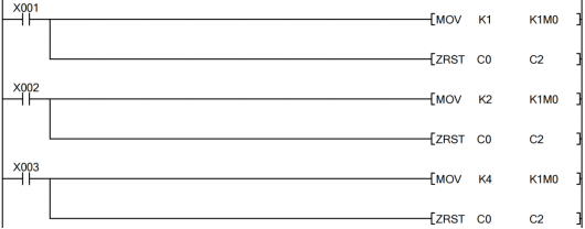
Figure 2 Mode Selection
(This is the position of the mode selection program diagram mentioned in the original text, core showing the application of MOV instruction and batch reset instruction.)
-
Pressing X1 (Mode 1): Executes MOV K1 K1M0 instruction, transferring the decimal number 1 into the 4-bit combination component K1M0 (corresponding to M0-M3), at this time only M0 is conductive, while M1, M2, and M3 are disconnected; simultaneously, the batch reset instruction (RST C0 C2) resets counters C0-C2, clearing historical counts.
-
Pressing X2 (Mode 2): Executes MOV K2 K1M0 instruction, only M1 is conductive, while the other flags are disconnected, and C0-C2 are reset.
-
Pressing X3 (Mode 3): Executes MOV K4 K1M0 instruction, only M2 is conductive, while the other flags are disconnected, and C0-C2 are reset.
Through this logic, X1-X3 establish a unique correspondence with M0-M2, making M0, M1, and M2 the exclusive flags for counts of 10,000, 20,000, and 30,000 respectively.
1.2 Counting and Alarm Logic: Flag-Linked Counter Output
The counting trigger and alarm logic centers around X0 (product sensor signal). Based on the conductive state of flags M0-M2, the corresponding counter is selected for counting. When the count reaches the set value, it triggers Y0 alarm, as shown in Figure 3:

Figure 3 Counting and Output Control
(This is the position of the counting and output control program diagram mentioned in the original text, showing the linkage between the counter and flags.)
-
When M0 is conductive (X1 mode): Each trigger of X0 will cause counter C0 to count (set value K10000). When the current value of C0 reaches 10,000, the normally open contact of C0 closes, triggering Y0 (buzzer) to sound the alarm.
-
When M1 is conductive (X2 mode): X0 triggers counter C1 to count (set value K20000), and when C1’s current value meets the standard, Y0 alarms.
-
When M2 is conductive (X3 mode): X0 triggers counter C2 to count (set value K30000), and when C2’s current value meets the standard, Y0 alarms.
The reset logic after the alarm is linked to mode selection: pressing any button among X1-X3 will trigger the reset of counters C0-C2, and Y0 will turn off, entering a new counting cycle.
Scheme 2: Dynamic Configuration of Counter Set Values – An Efficient and Simple Power Failure Saving Scheme
While Scheme 1 requires multiple counter resources, Scheme 2 achieves multi-threshold control using only one counter by “storing the set value in a register and having the counter call the register value as the target threshold”, while utilizing power failure holding components to save parameters.
2.1 Selection of Power Failure Holding Components
To avoid losing counting data and set values after the PLC is powered off, power failure holding registers and counters must be selected. According to the component characteristics of Mitsubishi FX3U PLC (as shown in Figures 4 and 5), D512-D7999 are power failure holding registers, and C100-C199 are power failure holding counters. This scheme selects D512 to store the set value, with C100 as the counting core.
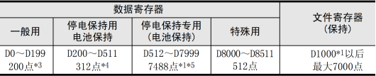
Figure 4 FX3U PLC Register Range

(This is the position of the register and counter range diagram mentioned in the original text, clarifying the address range of power failure holding components.)
2.2 Core Logic: Set Value Transfer and Counting Control
The core of Scheme 2 is to transfer different set values into D512 through mode buttons, with counter C100 using the value of D512 as the counting target. The specific logic is shown in Figure 6:
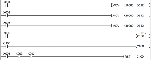
Figure 6 Control Using Register Set Values
(This is the position of the register set value control program diagram mentioned in the original text, showing the linkage between MOV instruction and counter.)
-
Set Value Transfer: When pressing X1, execute MOV K10000 D512, transferring 10,000 into D512; when pressing X2, MOV K20000 D512; when pressing X3, MOV K30000 D512.
-
Counting and Alarm: Each time X0 is triggered, counter C100 counts once (C100’s set value is D512). When C100’s current value reaches the set value stored in D512, the normally open contact of C100 closes, triggering Y0 to sound the alarm.
-
Reset Logic: When any button among X1-X3 is pressed, it triggers the reset of C100 (RST C100), Y0 stops output, and C100 restarts counting.
This scheme can achieve three-mode control using only one counter, occupying fewer components, and the power failure holding characteristics of D512 and C100 ensure that data is not lost after power failure, making it suitable for continuous production scenarios.
Scheme 3: Current Value Comparison of Counters – A Flexible Threshold Judgment Scheme
The first two schemes are centered on “fixed set values”, while Scheme 3 utilizes the logic of “comparing the current value of the counter with different thresholds”. By selecting comparison conditions through flags, it achieves multi-mode control, while using power failure holding intermediate relays to ensure stable mode states.
3.1 Selection of Power Failure Holding Intermediate Relays
In Mitsubishi FX3U PLC, intermediate relays M500 and above are power failure holding type (as shown in Figure 7). This scheme selects M512-M514 as mode flags to ensure that the mode state does not change after power failure.

Figure 7 FX3U PLC Intermediate Relay Range
(This is the position of the intermediate relay range diagram mentioned in the original text, clarifying the address range of power failure holding M points.)
3.2 Core Logic: Mode Flags and Current Value Comparison
The core of Scheme 3 is to keep counter C100 at the maximum threshold count (set value K30000) and select the “threshold that the current value must reach” through mode flags. The specific logic is shown in Figure 8:
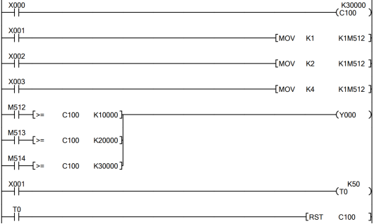
Figure 8 Control Using Current Value of Counter
(This is the position of the current value control program diagram mentioned in the original text, showing the application of flags and comparison instructions.)
-
Mode Flag Setting: Pressing X1 executes MOV K1 K1M512, only M512 is conductive; pressing X2 executes MOV K2 K1M512, only M513 is conductive; pressing X3 executes MOV K4 K1M512, only M514 is conductive (K1M512 is a 4-bit combination component starting from M512).
-
Counting and Comparison: X0 triggers C100 to count (set value K30000), while using comparison instructions to judge the relationship between C100’s current value and the corresponding threshold – when M512 is conductive, if C100 ≥ K10000, then Y0 alarms; when M513 is conductive, if C100 ≥ K20000, then Y0 alarms; when M514 is conductive, if C100 ≥ K30000, then Y0 alarms.
-
Reset Logic: Long pressing the X1 button for 5 seconds (can be achieved through a timer for delayed triggering) triggers the RST C100 instruction, resetting C100, Y0 stops output, and counting restarts.
The advantage of this scheme lies in its flexibility to add threshold modes; only new flags and comparison conditions need to be added, making it highly expandable and suitable for scenarios where production thresholds need frequent adjustments.
3. Comparison of the Three Schemes and Applicable Scenarios
All three schemes can meet the pipeline counting alarm requirements, but they each have their strengths and weaknesses in terms of component usage, expandability, and power failure saving. In practical applications, the choice should be based on on-site needs:
|
Comparison Dimension |
Scheme 1 (Flag + Multiple Counters) |
Scheme 2 (Dynamic Configuration of Set Values) |
Scheme 3 (Current Value Comparison) |
|---|---|---|---|
|
Component Usage |
3 counters, 3 M points, relatively high usage |
1 counter, 1 register, minimal usage |
1 counter, 3 M points, moderate usage |
|
Power Failure Saving |
Requires additional configuration for power failure holding counters |
Inherently supported (D512, C100 are power failure holding types) |
Inherently supported (M512+ are power failure holding types) |
|
Expandability |
New modes require additional counters, poor expandability |
New modes only require additional MOV instructions, moderate expandability |
New modes only require additional flags and comparison conditions, strong expandability |
|
Applicable Scenarios |
Simple scenarios with fixed modes and no need for expansion |
Efficient scenarios requiring continuous production and power failure saving |
Complex scenarios with variable thresholds and a need for flexible expansion |
4. Summary of Core Technical Points
This case study revolves around the application of the counter’s “current value” and “set value”, focusing on mastering the following PLC programming techniques:
-
Application of Combination Bit Components: By using combination bit components like K1M0, K1M512, etc., achieve interlocking control of multiple M points, simplifying mode selection logic and avoiding conflicts from multiple button triggers.
-
Selection of Power Failure Holding Components: Choose power failure holding type registers (D), counters (C), and intermediate relays (M) based on scenario needs to ensure that critical data and mode states are not lost after power failure.
-
Flexible Design of Counting Logic: Multiple counters are suitable for simple scenarios, dynamic configuration of set values is suitable for efficient scenarios, and current value comparison is suitable for expandable scenarios, requiring matching schemes based on on-site complexity.
-
Reliability of Reset Logic: Link reset instructions with mode selection to ensure that the counter can be quickly reset after an alarm, avoiding impacts on subsequent production.
The counter function of Mitsubishi PLC, while basic, can meet various needs from simple counting to complex multi-mode control through the flexible combination of “set value configuration” and “current value comparison”. The key lies in clearly understanding on-site requirements, reasonably selecting component types and programming logic, ultimately achieving a stable and efficient automation control scheme.
You’ve read this far, why not follow and give a thumbs up? The more people who share and like, the more motivated I am to update!