Differential Signaling
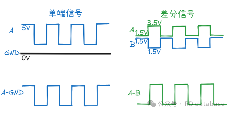
In the field of electronic communication and signal transmission, “differential signaling” is a frequently encountered technical term. From USB data cables and HDMI video cables to automotive CAN buses and industrial Ethernet, it relies on this method to achieve stable data transmission. The core logic is quite simple — using “comparison” instead of “individual judgment” significantly enhances the ability to resist interference compared to traditional single-ended signals.
Why is Differential Signaling Noise Resistant?
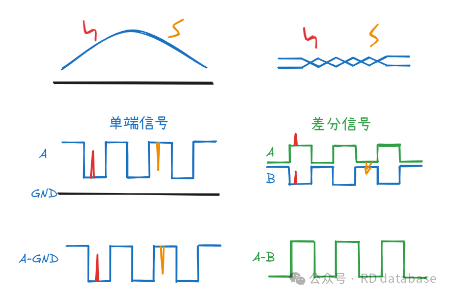
During signal transmission, interference is inevitable. For single-ended signals, the interference time and intensity between the signal line and ground line may not be the same, which we can refer to as differential mode interference. For differential signals, it is required that the trace lengths on the PCB are consistent, with two signal lines routed in parallel and twisted pairs used, so that the interference on both signal lines is essentially the same, which we call common mode interference. Differential mode interference cannot be eliminated through subtraction, while common mode interference can be largely eliminated after subtraction between the two signal lines. Therefore, differential signaling is more noise-resistant and widely used.
What is LVDS?
LVDS (Low-Voltage Differential Signaling) is essentially a “low-voltage version of differential signaling transmission technology”. Its core advantages include low voltage, low power consumption, high speed, and resistance to interference — it inherits the core mechanism of differential signaling, which relies on the voltage difference between two wires to determine logic, but achieves lower power consumption and higher transmission speeds by reducing the signal voltage amplitude (typically around 350mV), while maintaining the noise resistance of differential signaling.
Why is LVDS “Fast”?
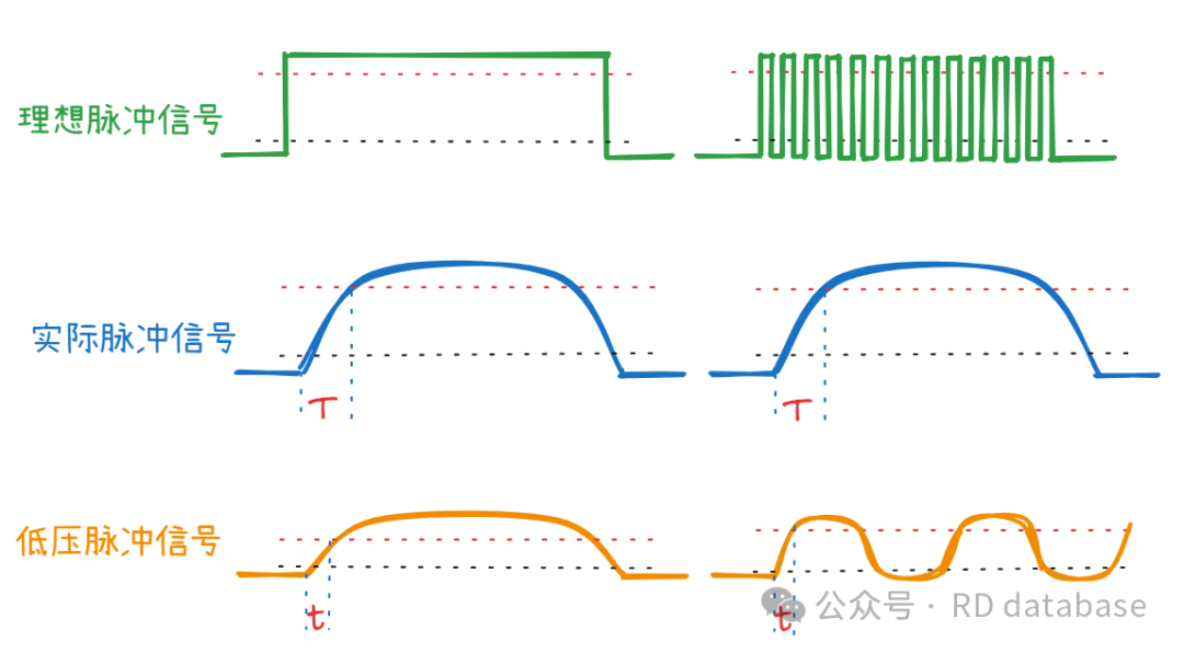
The ideal pulse signal is a step signal with a rise time of 0. However, in actual transmission lines, there are coupling/parasitic capacitances and inductances, causing the signal rise to always lag slightly. The higher the pulse voltage, the longer the time required for the voltage to rise, which naturally decreases transmission efficiency. Because LVDS transmits at low voltage, the pulse rise time is short, allowing it to accommodate more “data” within a limited time.