In the process of using Proteus, we can modify components in Proteus, such as changing the 74LS373 to a bus interface.
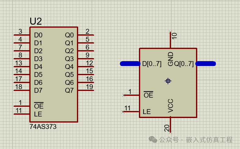
Steps:
1. Use the 2D Graphics Box Mode tool in  to draw the Device Body.
2. Use  to draw the pins using Device Pins Mode.
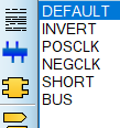
DEFAULT is for ordinary pins, BUS is for bus.
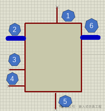
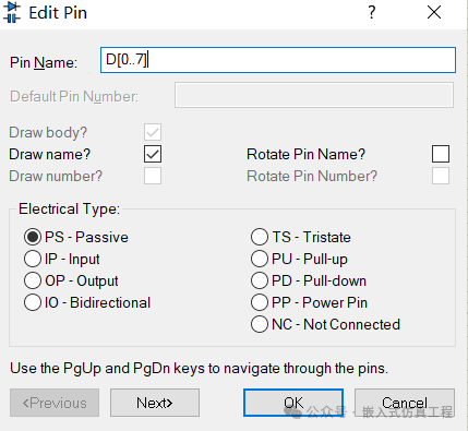
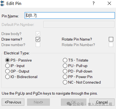
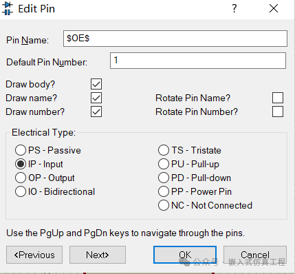
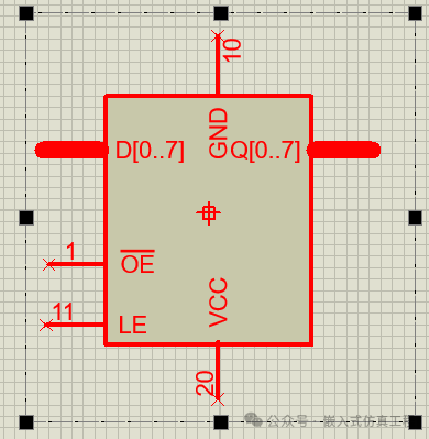
3. Modify the pin attributes. Explanation: 1 is GND, PIN10; 2 is D[0..7]; 3 is OE, PIN1; 4 is LE, PIN11; 5 is VCC, PIN20; 6 is Q[0..7]. First right-click then left-click 1, and enter the following data in the dialog box that appears; 5 is similar. GND and VCC need to be hidden, so do not select Draw body.
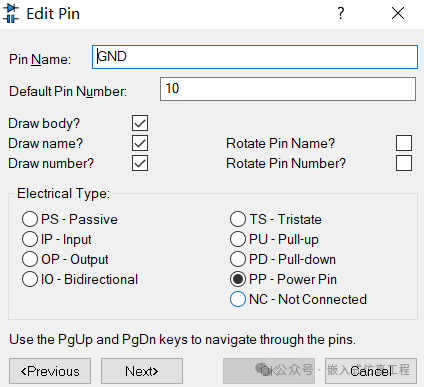
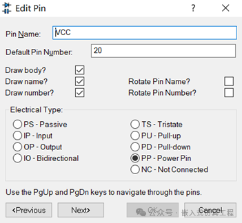
First right-click then left-click 2, and enter the following data in the dialog box that appears; 6 is similar.
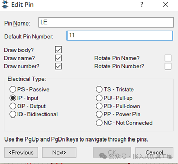
First right-click then left-click 3, and enter the following data in the dialog box that appears; 4 is similar.
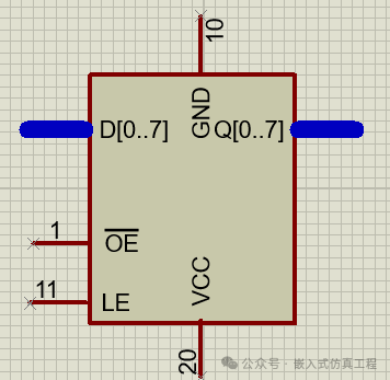
The final effect.
4. Add the center point.
Select the 2D Graphics Markers Mode tool in  to draw the center point, select ORIGIN.
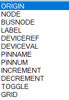
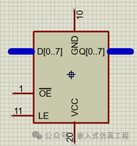
The position of the center point can be placed anywhere.
5. Package into the library.
First right-click to select the entire component.
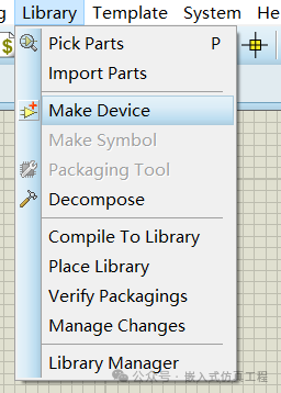
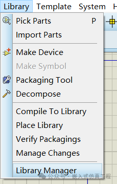
Then, select the menu “Library” Æ “Make Device” and click.
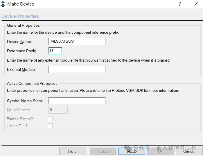
A dialog box will appear, and enter the following content.
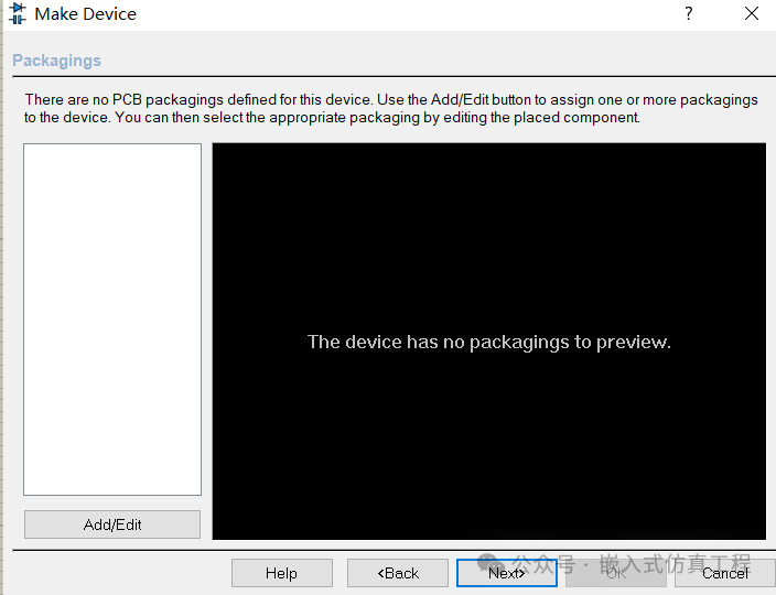
Click Next, select the PCB package, you can ignore this.
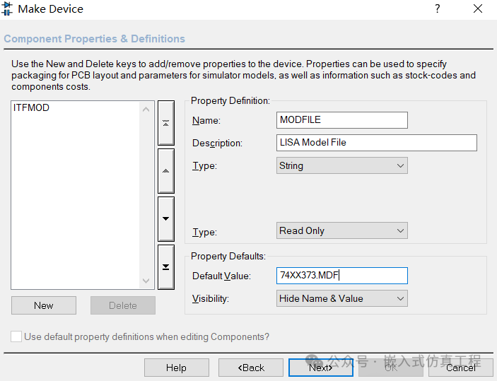
Click Next, set the component parameters.
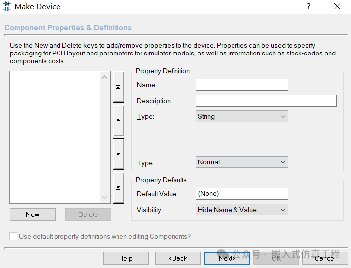
We need to add two attributes: {ITFMOD=TTLLS}, {MODFILE=74XX373.MDF}. Click New.
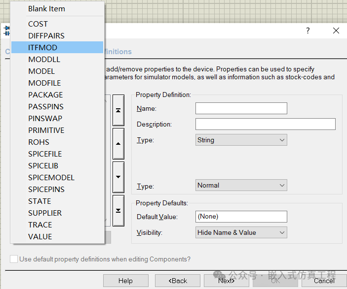
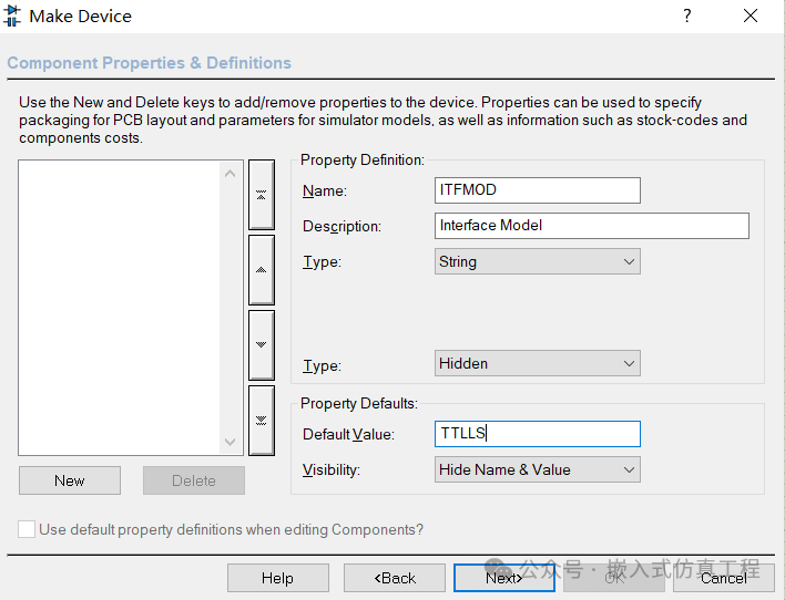
Continue clicking New.
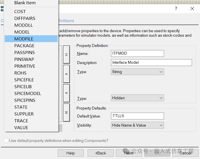
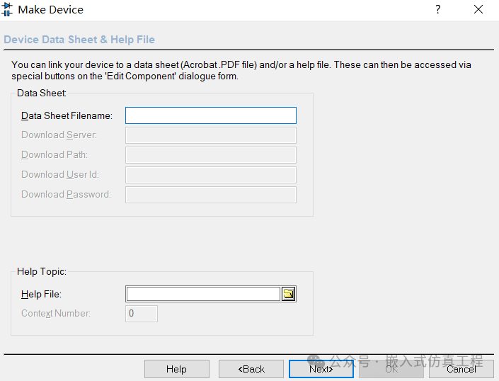
Click Next, this can be ignored.
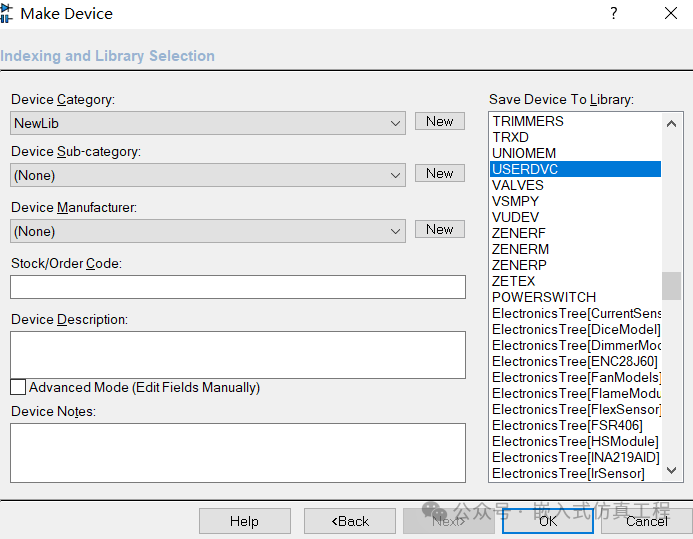
Click Next, select the component storage location, the default is in USERDVC, the left side is to select the category, it is best to create a new one, such as NewLib.
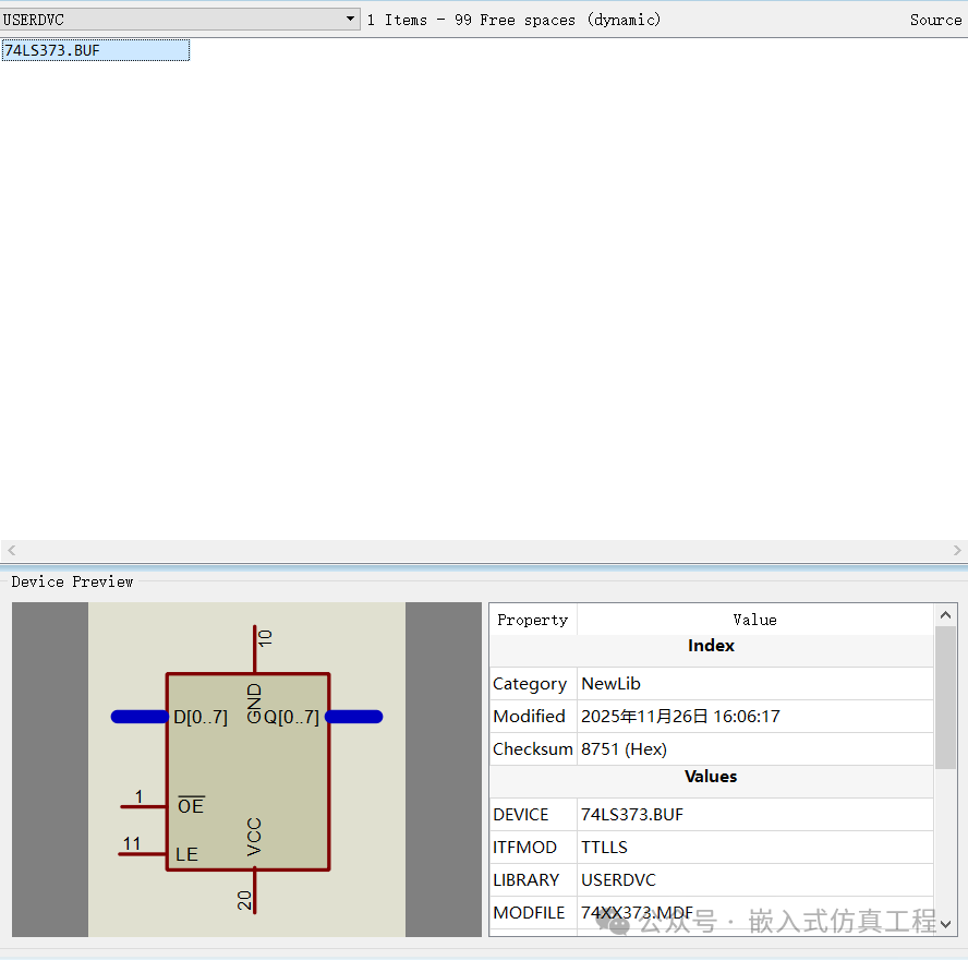
So far, the component modification is complete. You can use the library manager for your components.
Welcome to follow (operation reference article: send a message to the public account), click the blue text at the top “Embedded Simulation Engineering” or long press to identify the QR code to follow.