0x00 Official Repository
originbot: OriginBot robot end function package repository;
originbot_desktop: OriginBot desktop function package repository;
originbot_controller: OriginBot controller source code repository;
In this section, we will analyze the circuit principles and communication protocols of the lower machine controller;
0x01 Controller Repository Content
D:.├─firmware├─images├─material│ ├─Data Manual│ ├─Electrical Diagrams│ └─Communication Protocol├─source│ └─originbot_controller_project│ ├─DebugConfig│ ├─List│ ├─Obj│ ├─RTE│ │ └─_Project│ ├─Source│ │ ├─APP│ │ └─Drive│ └─STM32F10xLib│ ├─inc│ ├─Include│ ├─M3│ ├─src│ └─startup└─tools
firmware: Stores the lower machine firmware (*.hex) files;
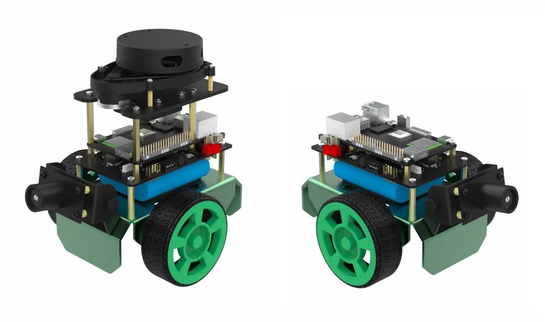
images: A photo of the car;
material: Data manual, electrical diagrams (AD schematic), communication protocol; This section is key;
source: Lower machine source program;
tools: FlyMcu.exe MCU downloader;
0x02 OriginBot_Controller Schematic
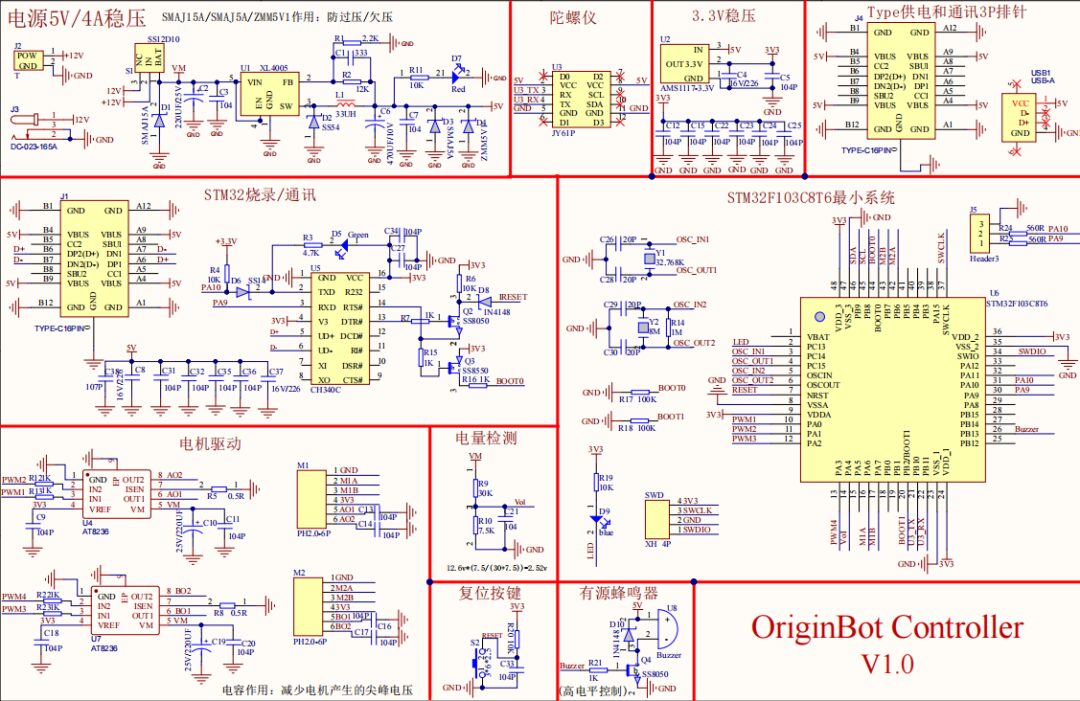
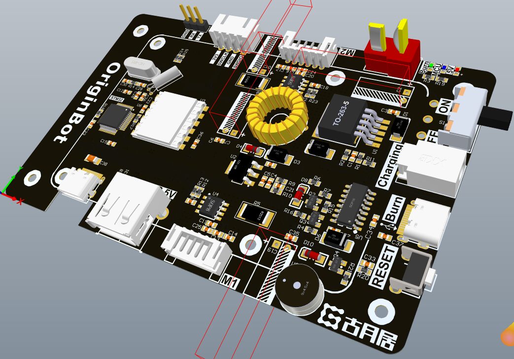
When designing hardware and software, it is essential to modularize, maintaining high cohesion and low coupling; PCB modular layout should leave interfaces between modules to form a complete system;
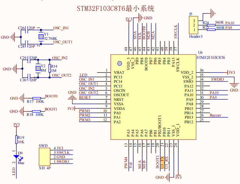
0x03 STM32F103C8T6 Minimal System
STM32F103C8T6 Microcontroller Introduction – CSDN Blog
(https://blog.csdn.net/fantastic_sky/article/details/110229474)
The STM32F103C8T6 microcontroller uses LQFP48 packaging design, with a total of 44 pins, including 16 pins from A0 to A15, 16 pins from B0 to B15, 3 pins from C13 to C15, and 2 pins from D0 to D1.
It is worth noting that the minimal core board connects C14 and C15 to a 32.768K crystal oscillator, and D0 and D1 connect to an 8MHz crystal oscillator.
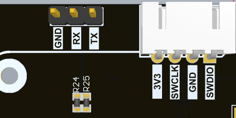
The control board can choose between two program download interfaces: ISP download and SWD download;
ISP Download
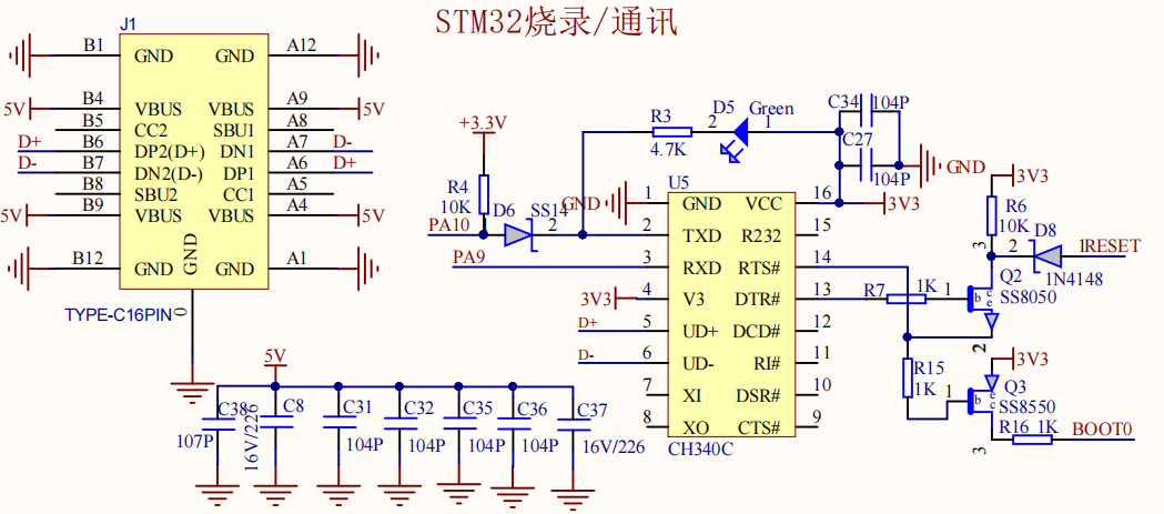
Programs can be downloaded via the Type-C socket or J5 header pins.
The serial chip used is CH340C, where the SS14 diode on pin 2 (TXD) prevents current backflow; when the MCU needs to reset for downloading, unsuccessful reset may also be caused by this reason.
CH340 circuit design voltage matching and current backflow prevention – CSDN Blog
(https://blog.csdn.net/chenhuanqiangnihao/article/details/113837550)
RTS# and DTR#, Q2, Q3 implement the automatic download circuit, the specific principle is as follows:
These two pins: DTR# and RTS# are output type, the MCUISP (one-click download tool) controls the high and low levels of these two pins, thereby controlling STM32’s BOOT0 and RESET.
The initial state of DTR# and RST# is high, and when downloading is enabled, DTR# remains high while RST# is pulled low. At this point, both transistors Q2 and Q3 conduct, making BOOT0 high and RESET low, then DTR# goes low, Q2 stops conducting, and the reset ends, at which point BOOT0 remains high. From the boot mode, it can be seen that the STM32’s boot mode changes to boot from system memory, enabling serial download, allowing communication between STM32 and the MCUISP download software for code downloading. Once the code download is complete, RST# goes high first, followed by DTR# going high. If DTR# goes high first, it will cause a reset.
D8 diode serves the same purpose, preventing backflow;
During the download process, the D5 LED will blink;
References:
Understanding the one-click download circuit (CH340) – CSDN Blog (https://blog.csdn.net/liukais/article/details/53926705)
STM32 one-click download CH340 DTR RTS and reset circuit NRST study notes – CSDN Blog (https://blog.csdn.net/weixin_70317234/article/details/127224498)
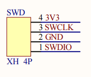
SWD Download
Using the SWD interface for downloading only requires connecting 3.3V (if the programmed board has its own power supply, the 3.3V pin does not need to be connected), GND, SWDIO (PA13), SWCLK (PA14), and RST (not necessary).
Using the SWD interface allows not only programming but also online simulation (debugging), allowing monitoring of registers and other data during the simulation process,
Motor control related pins:
PA0: PWM1
PA1: PWM2
PA2: PWM3
PA3: PWM4
PA6: M1A
PA7: M1B
PB6: M2A
PB7: M2B
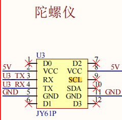
Gyroscope related pins:
PB8: SCL
PB9: SDA
PB10: U3_TX
PB11: U3_RX
Voltage detection pins:
PA4: vol
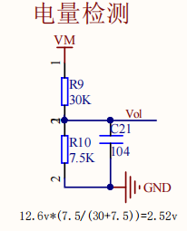
Voltage divider circuit;
LED & BUZZER:
PC13: LED
PA3: BUZZER
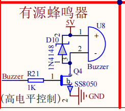
D10 serves as a flyback diode:
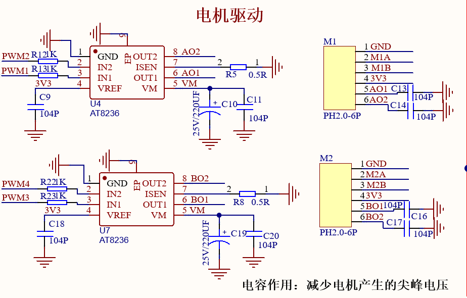
0x04 Motor Control Circuit
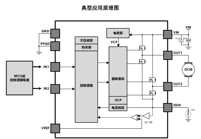
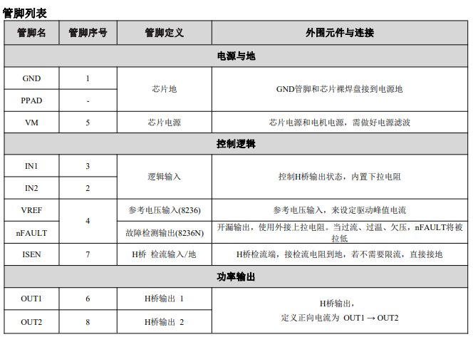
AT8236 is a DC brushless motor driver capable of bidirectionally controlling motors with a peak current of up to 6A. Using current decay mode, it can control motor speed via Pulse Width Modulation (PWM), while also having a low-power sleep mode.
Internal protection functions include overcurrent protection, short circuit protection, undervoltage lockout, and overtemperature protection. AT8236N provides a fault detection output pin. (Not included in this project)
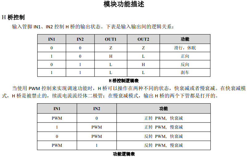
H-bridge fast decay cuts off the current quickly by controlling the opening and closing of switches, allowing the motor to stop quickly. Slow decay gradually reduces the current, allowing the motor to stop slowly.
Fast decay results in a rapid drop in motor speed, which may lead to lower position control accuracy. In contrast, slow decay keeps the motor at a higher speed for a longer time, thus achieving higher position control accuracy.
The main differences between fast decay and slow decay lie in the methods of current control and motor control accuracy.
0x05 Power Circuit Analysis
12V-5V Main Power Supply
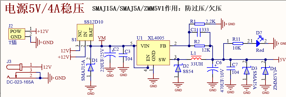
XL4005 is an efficient buck-type DC-DC converter chip widely used in power supply circuits. Its function is to step down a higher input voltage (+12V) to a lower output voltage (5V), with a maximum output current of 5A.
SMAJ15A: Unidirectional TVS 15V cutoff, 16.4A peak pulse; (D1)
SS54: Schottky diode; Voltage: 40V Current: 5A; Switching power supply inductance flyback effect; (D2)
SMAJ5A: Unidirectional TVS 5V cutoff peak pulse; (D3)
ZMM5V1: Zener diode, 5.1V; (D4)
FB is the feedback circuit, drawing power from the filter capacitor:
Minimize input-output return path; Reduce electromagnetic interference;
5V-3.3V Power Supply
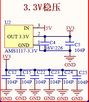
3.3V LDO uses AMS1117
Similar to DC-DC, minimize input-output return path, and place the filter capacitor close to the IC pins;
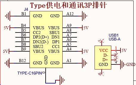
Type-C Interface Supplies Power to X3
0x06 Conclusion
Next, we can prepare to replicate this PCB


↑ Hot Course, Limited Time Coupons! 🎉 Grab Now ↑