What is the structure of a servo? The simplest servo control unit consists of a servo motor and a servo controller. Today, we will analyze the servo motor and the servo controller.
Principle of Motor Action
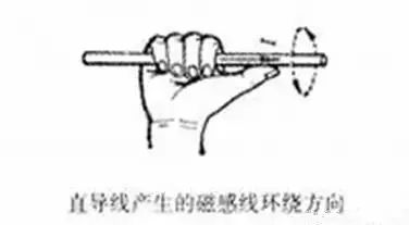
Right-Hand Rule (Ampere’s Law) – Current Generates Magnetic Field
Ampere’s Law, also known as the right-hand screw rule, describes the relationship between the direction of electric current and the direction of the magnetic field it generates. For a straight conductor carrying current: hold the conductor with your right hand, with your thumb pointing in the direction of the current, then your fingers will wrap around the conductor in the direction of the magnetic field lines; for a solenoid carrying current: hold the solenoid with your right hand, with your fingers curled in the direction of the current, then your thumb points to the N pole of the solenoid.

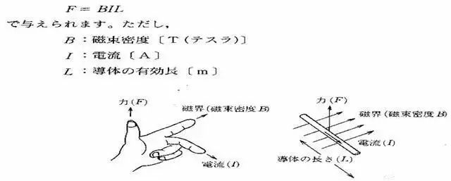
Fleming’s Left-Hand Rule – Force Generation
This rule determines the direction of force on a current-carrying conductor in an external magnetic field. Also known as the motor rule. Extend your left hand, with your thumb perpendicular to the other four fingers, palm facing the N pole, the four fingers represent the direction of current, and the thumb represents the direction of force on the conductor in the external magnetic field.
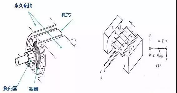
DC Servo Motor Structure
Servo Control Unit
※ The term SERVO comes from Latin, meaning ‘slave’, referring to a mechanism that achieves control of position, torque, speed, or acceleration of a mechanical system through closed-loop control. It is an execution unit in an automatic control system that converts electrical signals from the upper controller into angular displacement or angular velocity output on the motor shaft.
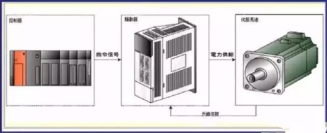
1. Controller: The device that outputs action command signals.
2. Driver: The device that receives control commands and drives the motor.
3. Servo Motor: The device that drives the controlled object and detects its state.
Types of Servo Motors
Servo motors can be broadly classified into the following three types:
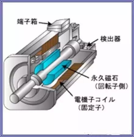
1. Synchronous: Uses permanent magnet synchronous motors, which generate power when the power is off, making braking easier. However, due to material limitations, the motor capacity is restricted. [Rotor: Permanent magnet; Stator: Coil]
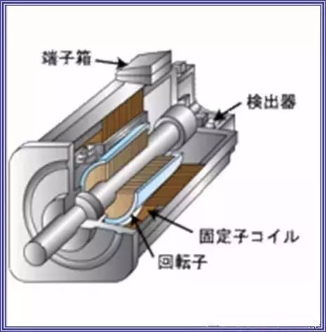
2. Induction: Induction motors are similar in construction to general-purpose motors, are robust, and perform well at high speeds, but they tend to overheat. Most large-capacity motors (over 7.5KW) are of this type. [Both rotor and stator are coils]
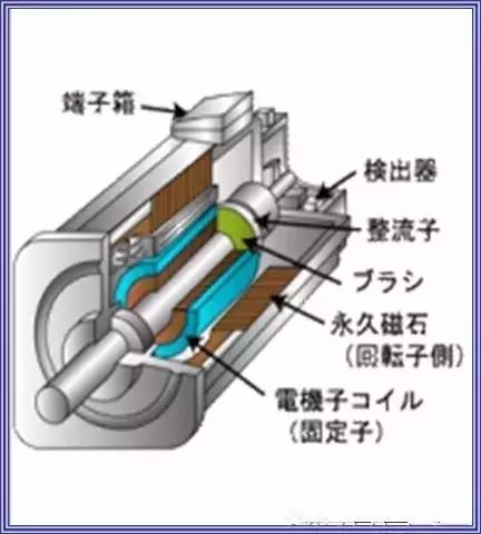
3. DC: DC servo motors have issues with brush wear generating dust, making them unsuitable for clean environments, and are primarily used in small capacities. [Rotor: Coil; Stator: Permanent magnet; Commutator: Brushes]
SM Synchronous Servo Motor
※ Advantages: 1. Maintenance-free. 2. Excellent environmental resistance. 3. Good torque characteristics, constant torque. 4. Can generate power for braking when the power is off. 5. Small size, light weight. 6. High efficiency.
※ Disadvantages: 1. The AMP is more complex than that of the DC type. 2. The MOTOR and AMP must be used in a 1:1 pairing. 3. Permanent magnets may demagnetize.
IM Induction Servo Motor
※ Advantages: 1. Easy maintenance. 2. Excellent environmental resistance. 3. Good torque characteristics at high speed. 4. Can be made in large capacities, with good efficiency. 5. Robust construction.
※ Disadvantages: 1. Small capacity models have poor efficiency. 2. The AMP is more complex than that of the DC type. 3. Cannot dynamically brake when the power is off. 4. Performance is affected by temperature changes. 5. The AMP and MOTOR must be used in a 1:1 pairing.
DC Servo Motor
※ Advantages: 1. Simple construction of the servo driver. 2. Can generate power for braking when the power is off. 3. Small size, low cost. 4. Good efficiency.
※ Disadvantages: 1. The commutator requires regular maintenance. 2. Brush wear generates carbon dust, making them unsuitable for clean environments. 3. Torque is poor at high speeds due to commutator brush issues. 4. Permanent magnets may demagnetize.
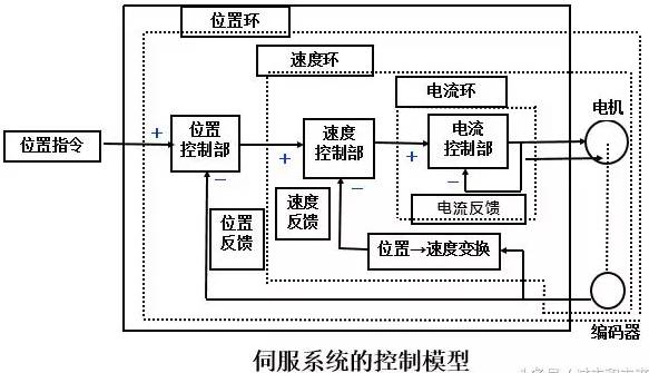
Servo Control Principles
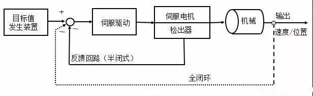
The greatest feature of the servo system: Control through feedback signals [which allows for comparison between command values and target values, greatly reducing errors].
What are feedback signals: After issuing commands to the controlled object, it accurately tracks and identifies the current value, and continuously feeds back the deviation of the control content. After the target reaches its destination, it feeds back the position value, repeating this process.
Control Process: Detecting the position of the mechanical body forms a closed loop, referred to as a full closed loop. In contrast, the loop system that detects the motor shaft end is called a half-closed loop.
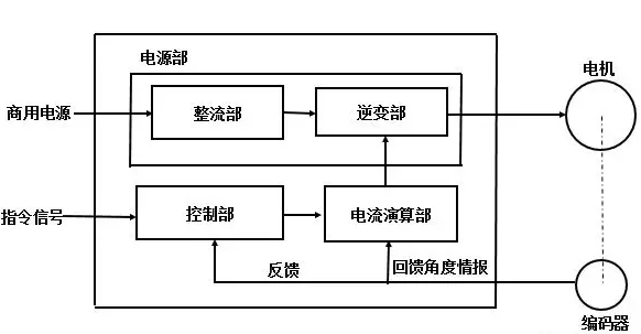
Internal Structure of the Servo Driver
Rectifier Section: The rectifier section converts AC power to DC power, and through capacitor filtering, produces a stable, ripple-free DC power supply.
Inverter Section: The SPWM signal from the control section drives the IGBT, converting the DC power into SPWM waveform to drive the servo motor.
Control Section: The servo unit uses a fully digital structure, supported by high-performance hardware to achieve software-based closed-loop control. Currently, all servos use DSP (Digital Signal Processing) chips, which can perform functions of position, speed, torque, and current controllers. They provide PWM control signals to the power drive unit and can receive and process position and current feedback, with communication interfaces.
Encoder: Servo motors are equipped with high-performance angular measurement encoders that can accurately measure the position of the rotor and the speed of the motor. The inverter uses new power electronic semiconductor devices. Currently, the output devices of servo control systems increasingly use high-frequency switching new power semiconductor devices, mainly including high-power transistors (GTR), power MOSFETs, and Insulated Gate Bipolar Transistors (IGBT). The application of these advanced devices significantly reduces the power consumption of the servo unit’s output circuit, improves the system’s response speed, and reduces operational noise.
It is particularly worth mentioning that the latest servo control systems have started using a new type of module that integrates control circuit functions and high-power electronic switching devices, referred to as Intelligent Power Modules (IPM). This device integrates input isolation, energy consumption braking, over-temperature, over-voltage, over-current protection, and fault diagnosis functions into a compact module. Its input logic level is fully compatible with TTL signals, allowing direct interfacing with microprocessor outputs. Its application significantly simplifies the design of servo units and achieves miniaturization and micro-miniaturization of servo systems.
Servo motors generally have three control methods: speed control, torque control, and position control.
Speed and torque control are both controlled using analog signals. Position control is achieved by sending pulses. The specific control method to be adopted depends on customer requirements and the type of motion functionality needed.
If there are no specific requirements for the speed or position of the motor, and only a constant torque output is needed, then the torque mode is used.
If there are certain accuracy requirements for position and speed, but real-time torque is not very critical, torque mode may not be convenient, and speed or position mode would be better. If the upper controller has good closed-loop control functionality, speed control will yield better results. If the requirements are not very high or there are basically no real-time requirements, position control mode does not impose high demands on the upper controller.
Regarding the response speed of the servo driver, torque mode has the least computational load, resulting in the fastest response to control signals; position mode has the highest computational load, resulting in the slowest response to control signals.
When there are high dynamic performance requirements for motion, real-time adjustments to the motor are necessary. If the controller’s computation speed is slow (such as with a PLC or low-end motion controller), position control should be used. If the controller’s computation speed is relatively fast, speed control can be used, moving the position loop from the driver to the controller, reducing the workload of the driver and improving efficiency (as in most mid to high-end motion controllers); if there is an even better upper controller, torque control can also be used, moving the speed loop away from the driver, which typically can only be done with high-end specialized controllers, and at this point, there is no need to use a servo motor.
To put it another way:
1. Torque Control:
The torque control mode sets the output torque size of the motor shaft to the outside through external analog signal input or direct address assignment. For example, if 10V corresponds to 5Nm, when the external analog signal is set to 5V, the motor shaft outputs 2.5Nm: if the motor shaft load is less than 2.5Nm, the motor rotates forward, if the external load equals 2.5Nm, the motor does not rotate, and if it exceeds 2.5Nm, the motor rotates backward (usually occurring under gravitational loads). The set torque can be changed instantly by altering the analog signal, or by modifying the corresponding address value via communication. This is mainly applied in devices that have strict requirements on material stress during winding and unwinding, such as wire winding devices or fiber optic pulling equipment, where the torque setting must be adjusted according to changes in the winding radius to ensure that the material’s stress does not change with the winding radius.
2. Position Control:
Position control mode generally determines the rotation speed through the frequency of externally input pulses and the rotation angle through the number of pulses. Some servos can also directly assign values for speed and displacement via communication. Because position mode can strictly control both speed and position, it is generally used in positioning devices. Application areas include CNC machine tools, printing machinery, etc.
3. Speed Mode:
Speed can be controlled through analog signal input or the frequency of pulses. In the case of upper control devices with external PI control, speed mode can also perform positioning, but the motor’s position signal or the direct load’s position signal must be fed back to the upper level for computation. Position mode also supports direct load external loop detection of position signals, where the encoder at the motor shaft only detects the motor speed, and the position signal is determined by the direct final.
Business Cooperation: 010—88379790 ext 802
Disclaimer: This article is a network reprint, and the copyright belongs to the original author. However, due to numerous reprints, it is impossible to confirm the true original author, hence only the source is indicated. If the videos, images, or text used in this article involve copyright issues, please inform us as soon as possible, and we will confirm the copyright based on the proof materials you provide and pay remuneration according to national standards or delete the content immediately! The content of this article reflects the original author’s views and does not represent the views of this public account or take responsibility for its authenticity.