
For MODBUS communication between S7-1200 and V20, the S7-1200 PLC needs to add a CM1241 RS485 communication module.
The V20 inverter is connected to the PLC via RS485 cable, using the standard MODBUS communication protocol. Through MODBUS communication, the PLC sends commands to the V20 inverter to start, stop, and adjust the frequency.
The specific wiring is shown in the figure below:
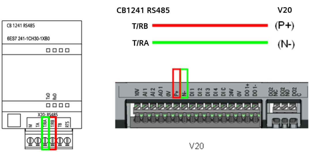
▲ Figure 1-1: Wiring of S7-1200 CB1241 and V20 Communication
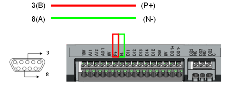
Figure 1-2: Wiring of S7-1200 CM1241 and V20 Communication
The network topology diagram for communication between V20 and PLC, the matching terminal network termination resistors can be purchased from Siemens distributors. The order number for the termination resistor is: 6SL3255-0VC00-0HA0, the specific wiring is shown in the figure below:
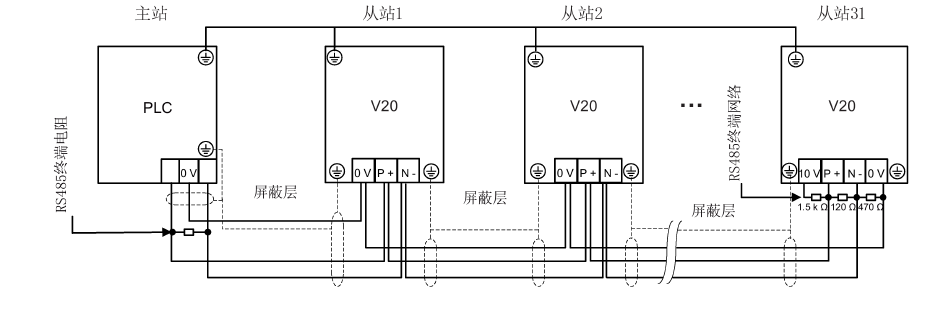
▲ Figure 1-3: PLC and V20 Communication Wiring Diagram
Common MODBUS registers for V20, as shown in Table 2-1:
|
Type |
Register Address |
Description |
Access Type |
Scaling Factor |
Read |
Write |
|
Control Data |
40100 |
Control Word |
R/W |
1 |
PZD1 |
PZD1 |
|
40101 |
Main Set Value |
R/W |
1 |
PZD2 |
PZD2 |
|
|
Status Data |
40110 |
Status Word |
R |
1 |
PZD1 |
PZD1 |
|
40111 |
Actual Speed Value |
R |
1 |
PZD2 |
PZD2 |
|
|
P1120 |
40322 |
Ramp Up Time |
R/W |
100 |
P1120 |
P1120 |
|
P1121 |
40323 |
Ramp Down Time |
R/W |
100 |
P1121 |
P1121 |
▲ Table 2-1: Common MODBUS Registers for V20
V20 Parameter Settings
Communication related parameter settings for the V20 inverter, as shown in Table 2-2:
|
Parameter Number |
Parameter Value |
Description |
|
P2010 |
6 |
Set communication baud rate to 9600bps |
|
P2021 |
1 |
Set inverter slave address to 1 |
|
P2023 |
2 |
Select communication protocol as Modbus |
|
P2034 |
2 |
Select even parity |
|
P2035 |
1 |
1 stop bit |
▲ Table 2-2: Related Parameters for V20 Inverter
Note: You can also directly choose to connect macro CN011, after which the default settings are as shown in Table 2-3:
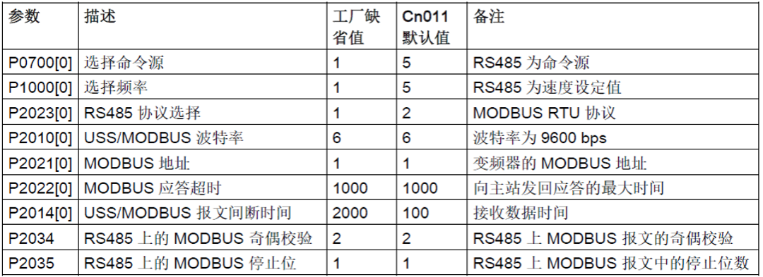
▲ Table 2-3: Parameter Settings for Connecting Macro CN011
The PLC programming is as follows:
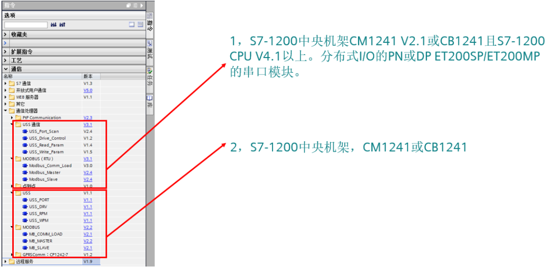
Initialize the Modbus communication interface, ensuring that the baud rate and parity on the PLC side match the settings of the V20.
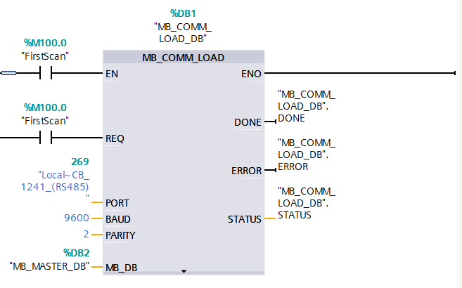
Note:
PORT: Communication port ID.
BAUD: Baud rate.
PARITY: Parity setting.
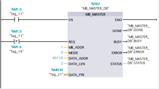
MB_DB: Background DB block 2 for MB_MASTER, write the required control word through register 40100.
Note:
1. The 10th bit of register 40100 must be set to 1 to allow PLC control.
2. Upon first power-up, write the hexadecimal 047E, and then write 047F to start the drive.
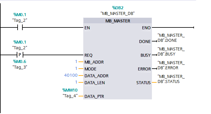
MB_ADDR: Modbus RTU slave address.
MODE: Mode selection, 0 for read, 1 for write.
DATA_ADDR: Register address.
DATA_LEN: Data length, depending on the accessed parameter (in words).
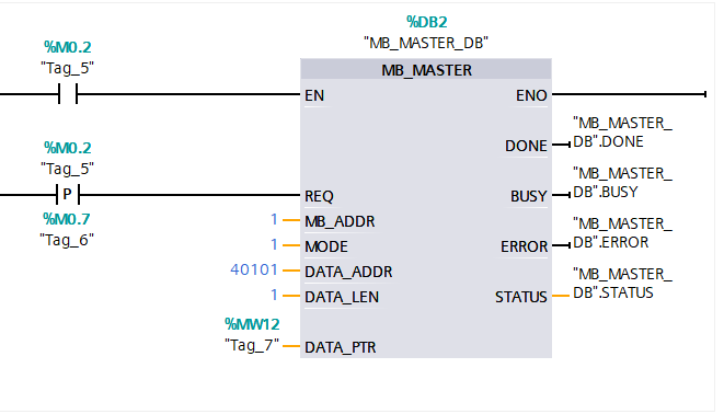
DATA_PTR: Pointer to the CPU’s storage address, from which data is read or written. 3. Write the speed set value into register 40101, where the hexadecimal 0-4000H corresponds to 0-100% of the P2000 base frequency.
4. Read two words at once through address 40110, which directly reads the status word (40110) and actual frequency (40111).
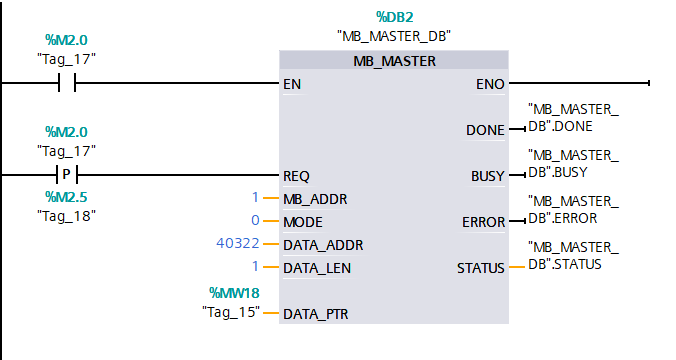
5. Read ramp-up time through address 40322.
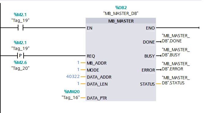
6. Write ramp-up time through address 40322.
Complete Question Bank for Junior Electrical Worker Exam 2021 (Includes Answers)
Is troubleshooting inverter faults difficult? Just one click!
Can you brush through all electrical exam questions with one click? Don’t you own this amazing tool yet?
Which of the five major electrical drawing software (CAD, Eplan, CADe_simu…) do you pick?
Latest Electrical CAD Drawing Software, with super detailed installation tutorial!
Latest Electrical Drawing Software EPLAN, with super detailed installation tutorial!
Common Issues for Beginners Using S7-200 SMART Programming Software (Includes Download Links)
Comprehensive Electrical Calculation EXCEL Sheets, automatically generated! No need to ask for electrical calculations!
Bluetooth Headphones, Electrical/PLC Introductory Books are yours to claim! Come and get your electrical gifts!
Basic Skills in PLC Programming: Ladder Diagrams and Control Circuits (Includes 1164 Practical Cases of Mitsubishi PLC)
Still can’t understand electrical diagrams? Take away the basics of electrical diagram recognition and simulation software, quickly get started with theory and practice!
12 Free Electrical Video Courses, 10GB Software/E-books, and 30 Days of Free Live Electrical Courses are being given away!