Click the ” Jicheng Training ” above, select “Pin Public Account“
150,000+ industrial control professionals are following this WeChat platform: technical sharing, learning exchange, industrial control videos
(1) Modbus Communication
Modbus communication of S7-200:
S7-200 only supports the Modbus RTU protocol and does not support the Modbus ASCII protocol;
Modbus is a master/slave communication mode with a single master station. There can only be one master station on a Modbus network, while there can be several slave stations (as shown in the figure below). The address range for slave stations is 1-247;

A transmission character in Modbus communication should include one start bit, 8 data bits, 1 or 0 parity bits (odd/even parity or no parity can be chosen), and one stop bit.
The RS485 half-duplex communication implemented on the S7-200 CPU communication port uses the free port function of S7-200.
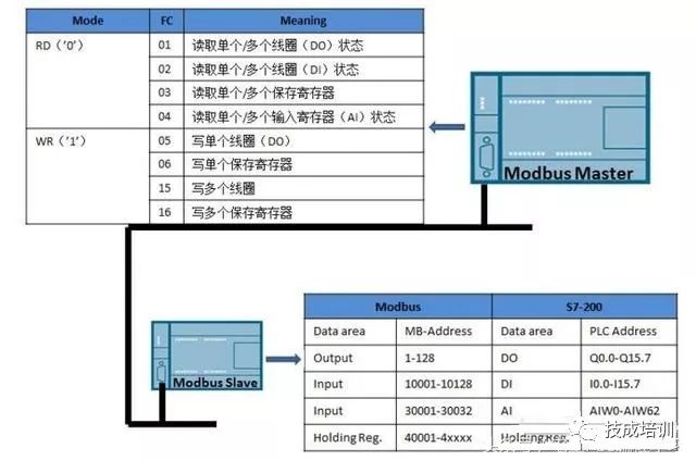
The above figure shows a typical network structure of a master station and slave station. For the Modbus master station, it can perform read or write operations on slave stations, where the supported function codes (FC, Function Code) include the functions described in the table on the left side of the master station, for example, function code ’01’ indicates reading the status of single/multiple coils (DO) or function code ’04’ indicates reading the status of single/multiple input registers (AI).
For the slave station, we only need to establish the correspondence between the Modbus standard address and the slave station address. The correspondence between the S7-200 slave station and the Modbus standard is shown in the table on the right side of the slave station.
The left side of the table shows the Modbus standard address codes, where 1-128 corresponds to S7-200’s Q0.0-Q15.7, 10001-10128 corresponds to S7-200’s I0.0-I15.7, 30001-30032 corresponds to AIW0-AIW62, and 40001-4xxx corresponds to the holding registers of S7-200 (V area), with a range of T-T+2*(xxxx-1), where T is the starting address of the V area, determined by the instructions of the Modbus slave.
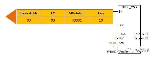
The master station command of Modbus is called MBUS_MSG, which can send the Modbus standard message to the slave station. For example, in the above example, the first byte of the slave station is 03, indicating the address of the slave station, FC function code is 03, indicating reading single/multiple holding registers, the Modbus standard address is 40001, and the length is 10. With different function codes, the format of the message will change accordingly, and the specific message format needs to be referred to in the Modbus communication manual.
The slave station instruction is MBUS_SLAVE, which will return a message according to the requirements of the message received from the master station. For example, in the above example, the returned format has the first byte as the address of the slave station, the second byte as the function code, and the third byte as the data returned to the master station, thus completing a Modbus communication request and response process.
(2) Installation and Invocation of Modbus Library Files
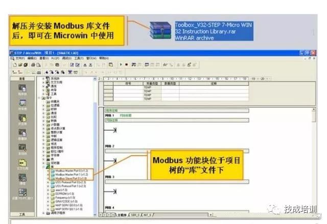
If you want to use the Modbus instruction library, you first need to apply for the instruction library named ‘Toolbox_V32-STEP 7-Micro WIN’ from the internet or Siemens customer service personnel, unzip it, and install it into Micro WIN to use. After installation, the three libraries marked in the above figure will appear in the Micro WIN library files, where Port0 and Port1 can be used as Modbus Master, while only Port0 can be used as Slave.
(3) Usage of Modbus Library Files
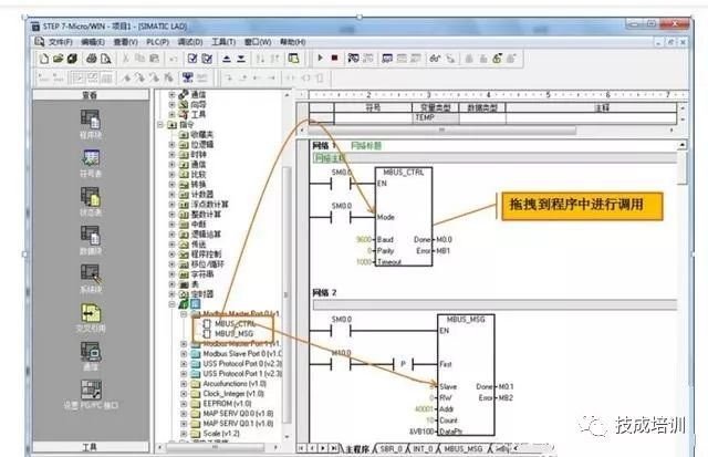
The usage is very simple. Open the Modbus master station instruction library, and the corresponding instruction blocks will appear. Just drag and drop the instruction blocks into the program for invocation.
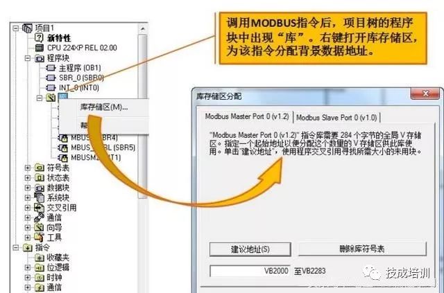
When invoking Modbus library instructions, it is important to remember to allocate a storage area for the Modbus library files. The specific method is to right-click on the library, then select the storage area, and in the pop-up dialog, you can choose the suggested address, which automatically allocates a range of addresses that are not used in the program, or manually fill in the starting address. This range must not conflict with other data areas in the program; otherwise, the Modbus function will not work properly.
The so-called storage area is actually a part of the background data that the Modbus instruction library needs to work properly. As long as the range is allocated properly and does not conflict with other addresses in the program, it can work normally.
(4) Modbus Slave Instructions
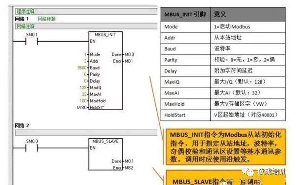
There are two slave instructions. The first is the initialization instruction for the slave (MBUS_INIT), and the other is the MBUS_SLAVE slave instruction. What does the Modbus slave initialization instruction involve? First, the first pin Mode indicates that when equal to 1, Modbus is started, and when equal to 0, Modbus is closed. Addr indicates the address of the slave station, Baud indicates the baud rate, Parity is the parity check, where 0 is no parity, 1 is odd parity, and 2 is even parity. Delay is the delay between additional characters, MaxIQ indicates the maximum I/Q address (default 128), MaxAI indicates the maximum AI length (default 32), MaxHold indicates the maximum V storage area (VW), and the most critical is HoldStart, which indicates the starting address of the V area (corresponding to 40001). As previously mentioned, when S7-200 is used as a slave, its V area address corresponding to the starting address of the Modbus standard address can be changed, which is set here. In this example, if HoldStart is set to VB0, then the address corresponding to 40001 is VW0, 40002 corresponds to VW2, 40003 corresponds to VW4, and so on. Each standard Modbus address code corresponds to one Word, and similarly, if this is set to VB100, then 40001 corresponds to VW100, 40002 corresponds to VW102, and so on.
This initialization instruction only needs to be called once, so in the above example, it is executed once at power-up using SM0.1.
The MBUS_SLAVE function block must be used with the previous condition being 1 all the time, as shown in the above example using SM0.0.
Note: Due to the length of the article, the content for points 5, 6, and 7 will be shared tomorrow, stay tuned~
Share more, gain more knowledge 
Click Read Original to learn about electrical engineering, PLC, frequency servo, CNC robots, and more.