For more content, please click above to follow ABB Robot Practical Skills
You can also click on the public account below Classic Articles to browse more content
For reprints, please leave a message in the background first, let’s support original content together and promote the use and development of robots
This public account provides technical support for various ABB robot applications, simulations, and graduation projects. For details, please leave a message in the background
This public account sincerely hopes to cooperate with various robot training institutions and robot usage units to provide technical support, for details, please leave a message in the background
1. Modbus was developed by MODICON in 1979 and is an industrial fieldbus protocol standard. In 1996, Schneider Electric introduced the Modbus protocol based on Ethernet TCP/IP: Modbus TCP. Communication follows the master/slave model.
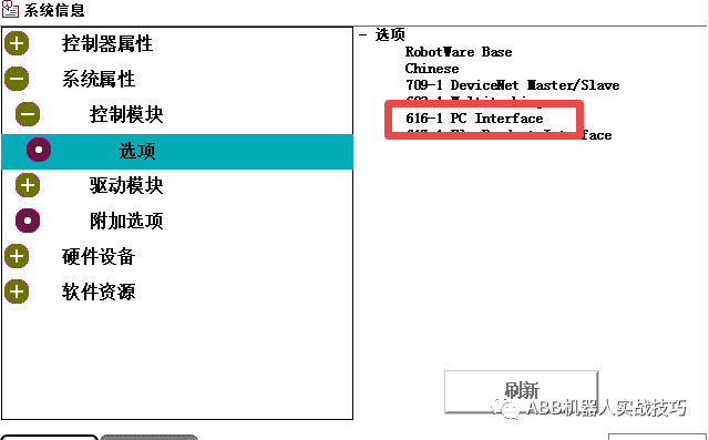
2. MODBUS/TCP is based on Ethernet, so ABB robots need the 616-1 PC INTERFACE option when in use.
3. ABB does not provide standard MODBUS related processing functions. To use Modbus/TCP, you can use ordinary sockets for sending and receiving, combined with Modbus definitions to process the data.
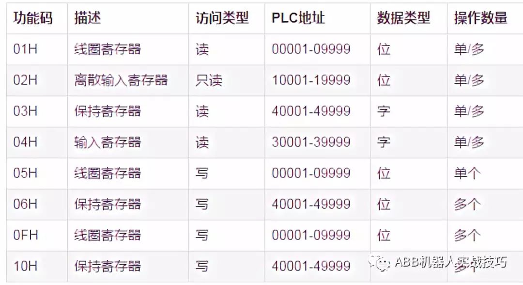
4. Modbus communication between the robot and PLC is realized through related function codes, as shown in the figure below (in hexadecimal).
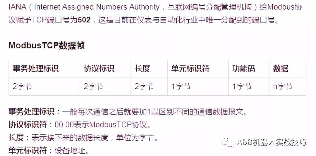
5. The Modbus TCP data frame is explained as follows:
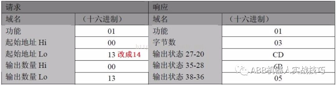
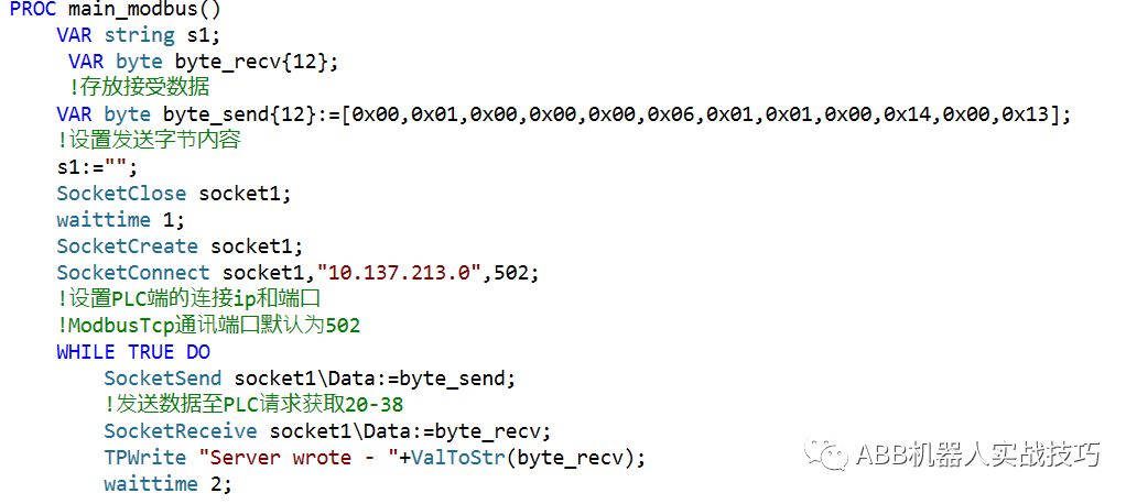
6. Here is an example where the robot requests the PLC to read the status of coils from address 20 to 38. The sending code is as follows, where (all information is in hexadecimal):
0x00,0x01,0x00,0x00,0x00,0x06,0x01,0x01,0x00,0x14,0x00,0x13
The red part represents the first to seventh bytes:
First and second bytes: Transaction identifier, the PLC will return the same value.
Third and fourth bytes: 00,00 Modbus TCP protocol.
The fifth and sixth bytes indicate the total number of bytes starting from the seventh byte.
The seventh byte: Device address.
The black part represents the specific content:
The eighth byte is the function code. Here, the request is to read the coil status, so it is 0x01.
The ninth and tenth bytes: Starting address (here both are in hexadecimal) address 20, corresponding to hexadecimal 0x14.
The eleventh and twelfth bytes: The number of coils starting from the starting address, a total of 19, corresponding to hexadecimal 0x13.
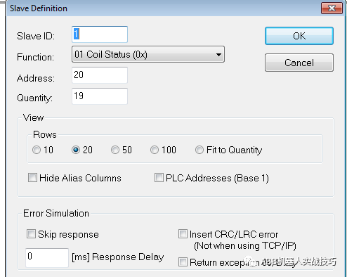
7. You can download the Modbus Slave software for simulation. Click setup to complete the following settings and run:
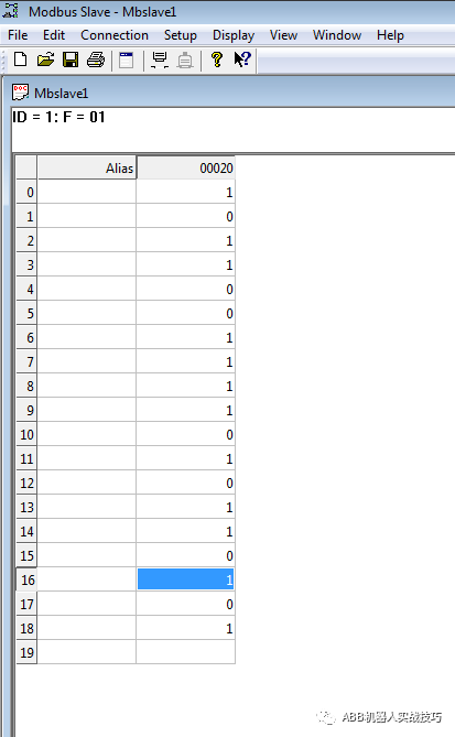
The data in the above figure is set to 0xCD, 0x6B, 0x05.
8. After the robot sends the above data content, it will receive the following information:
0x00,0x01,0x00,0x00,0x00,0x06,0x01,0x01,0x03,0xCD,0x6B,0x05
The red part is explained the same as in part 6.
The eighth byte, the function is to read the coils.
The ninth byte, 0x03 indicates the number of bytes starting from the tenth byte.
The tenth byte represents coils 27-20, 11001101.
The eleventh byte represents coils 35-28, 01101011.
The twelfth byte represents coils 43-36, 00000101 (getting data for 38-36 and 43-39 with 0 padding).
9. The robot code is as follows:
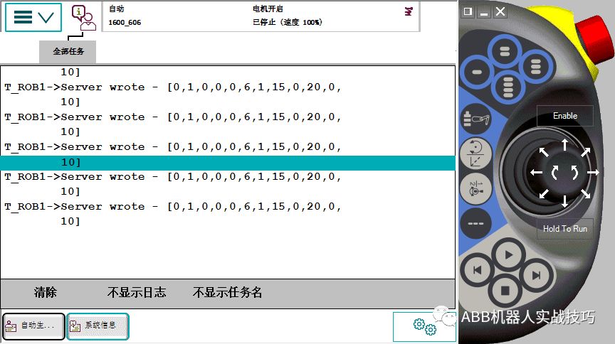
After running, the robot receives the data as follows:

Since the robot displays in decimal, 205 corresponds to 0xCD, 107 corresponds to 0x6B, and 5 corresponds to 0x05.
10. To write values to a total of 10 coils from address 20 to 29, refer to the function code in step 4 which is 0x0F. The sending data is as follows:
0x00,0x01,0x00,0x00,0x00,0x09,0x01,0x0F,0x00,0x14,0x00,0x0A,0x02,0xFF,0x03
The red part represents the first to seventh bytes:
First and second bytes: Transaction identifier, the PLC will return the same value.
Third and fourth bytes: 00,00 Modbus TCP protocol.
The fifth and sixth bytes indicate the total number of bytes starting from the seventh byte.
The seventh byte: Device address.
The black part represents the specific content:
The eighth byte is the function code. Here, the request is to write the coil status, so it is 0x0F.
The ninth and tenth bytes: Starting address (here both are in hexadecimal) address 20, corresponding to hexadecimal 0x14.
The eleventh and twelfth bytes: The number of coils starting from the starting address, a total of 10, corresponding to hexadecimal 0x0A.
The thirteenth byte: Indicates the remaining total number of bytes starting from the fourteenth byte.
The fourteenth and fifteenth bytes: Write values. If all 10 coils are set to 1, then bits 27-20 will be 11111111 corresponding to hexadecimal 0xFF, and bits 35-28 will be 00000011 corresponding to hexadecimal 0x03.
11. After sending the above content, the robot will receive the following data:
0x00, 0x01, 0x00, 0x00, 0x00, 0x06, 0x01, 0x0F, 0x00,0x14,0x00, 0x0A
The red part is the same as in part 10.
The black part represents the specific content:
The eighth byte is the function code. Here, the request is to write the coil status, so it is 0x0F.
The ninth and tenth bytes: Starting address (here both are in hexadecimal) address 20, corresponding to hexadecimal 0x14.
The eleventh and twelfth bytes: The number of coils starting from the starting address, a total of 10, corresponding to hexadecimal 0x0A.
12. The robot code is as follows:
13. After running, you can see that bits 29-20 are all set to 1 in the simulation software.
14. The robot receives data as follows (the robot side displays in decimal):
Decimal 15 corresponds to 0xFF, decimal 20 corresponds to 0x14, decimal 10 corresponds to 0x0A.
********************************
How to Get More Classic Articles?
Follow the public account ABB Robot Practical Skills, click on the bottom of the page Classic Articles and Configuration to see more classic content
Click Read the original text to learn about RobotStudio simulation and obtain complete teaching videos.
More content
★ Based on PCSDK to transfer files to HOME and load
★ RMQ communication – communication with PC
★ Use timed interrupts to send robot positions to PLC
★ Accurate early triggering of signals
★ Calibration of positioning machines
★ Secrets of ABB robot zero point calibration
★ Create UDP communication
★ Left multiplication and right multiplication of rotation posture
★ Control robot start and stop via socket
★ Robot drawing Doraemon
★ On Children’s Day, the robot draws Conan
★ SearchL simulation workstation
★ Path offset real-time correction function
★ Undo processing program
★ Use group output to send ASCII codes
Robot PROFINET does both CONTROLLER and DEVICE
★ Voice control ABB robot
★ Mobile access web control robot
★ YUMI servo hand simulation production
★ Custom servo welding gun
★ Create a conveyor chain grabbing and transporting palletizing workstation
★ Random material generation and grabbing
★ Four-axis robot defines TCP
★ Recalculate TCP after tool replacement
★ Custom external axis – positioning machine
★ Teach four points to complete palletizing
★ Multimove of dual robots and positioning machines
Robotware 6.08 collision prediction enable and disable
SMB board pin explanation
Coupling limits of four and six joints
Calculate the distance between two points
New I/O DSQC1030 configuration
ABB robot configuration of servo welding gun
How to move after robot collision
Set angle path fault notification off
External PLC selects robot program
One-click return to HOME program
Modification of the upper and lower limits of each axis of the robot
Wobjdata data explanation
Relationship between conveyor chain tracking and vision
Wiring for emergency stop and automatic stop
For more expert explanation videos, you can visit https://www.aiimooc.com to search for ABB or scan the following QR code