
Before we start this topic, we should understand a commonly confused issue.
The difference between RS485 and MODBUS:
RS485 is a physical interface, simply put, it is hardware.
MODBUS is an internationally standardized communication protocol used for data exchange between devices from different manufacturers (generally for industrial purposes); the so-called protocol can also be understood as a “language” mentioned by someone above, simply put, it is software.
Generally, two devices transmit data through the MODBUS protocol:
Initially, RS232 was used as the hardware interface (which is the serial communication port on a regular computer);there are also RS422 and commonly used RS485, which is widely used in general industrial sites due to its long transmission distance.
The MODBUS protocol is divided into three modes: MODBUS RTU, MODBUS ASCII, and the later developed MODBUS TCP.
The first two (MODBUS RTU, MODBUS ASCII) use serial communication (RS232, RS422, RS485) as their physical hardware interface.
MODBUS TCP, on the other hand, was developed to align with the current global trend, where everything can be connected via Ethernet or the Internet to transmit data. Thus, the MODBUS TCP mode was created, where the hardware interface is the Ethernet port, which is the network port commonly used on our computers.
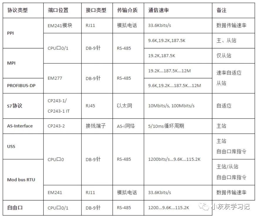
Next, we can understand the various communication protocols supported by the S7-200 PLC through an image.
1. PPI Communication
PPI communication is a protocol developed by Siemens specifically for the S7-200 series PLC. It is built into the S7-200 CPU. The PPI protocol is physically based on the RS-485 port and can achieve PPI communication through shielded twisted pair cables.
The PPI protocol is a master-slave protocol. The master device sends requests to the slave device, and the slave device responds; the slave cannot actively send information. The master communicates with the slave through a shared connection managed by the PPI protocol. The PPI protocol does not limit the number of masters communicating with any slave, but there cannot be more than 32 masters in a network. The most basic use of the PPI protocol is to allow Siemens Step7-Micro/Win programming software to upload and download programs and for Siemens human-machine interfaces to communicate with PCs.
2. MPI Communication
MPI (Multipoint Interface) is the interface for SIMATIC S7 multipoint communication, suitable for communication between a small number of stations, mostly used for short-distance communication between host computers and a few PLCs.
By connecting the MPI programming port of the S7-300 or S7-400 CPU with the PPI communication port of the S7-200 CPU via Profibus cables and connectors, as well as connecting to the host computer’s network card (MPI/DP port) through Profibus or MPI cables, communication can be established. The network can also consist solely of PLCs without including a PC. The communication rate of MPI is 19.2k to 12 Mbit/s, but the maximum rate for MPI networks directly connected to the S7-200 CPU communication port is usually 187.5 kbit/s (limited by the maximum communication rate of the S7-200 CPU). Up to 32 stations can be on an MPI network, with a maximum communication distance of 50 meters (when the communication baud rate is 187.5 kbit/s); longer distances can be extended through RS-485 repeaters. MPI allows for master-master and master-slave communication, with a maximum of 4 connections per S7-200 CPU communication port. The MPI protocol cannot communicate with an S7-200 CPU acting as a PPI master; when communicating between S7-300 or S7-400 and S7-200, the S7-200 CPU must not serve as a PPI master, and Micro/Win cannot access an S7-200 CPU acting as a PPI master via the MPI protocol. The S7-200 CPU can only act as an MPI slave, meaning S7-200 CPUs cannot communicate with each other over an MPI network, but can only communicate with each other via PPI.
3. Modbus Communication
Modbus was invented by Modicon (now a brand of Schneider Electric) in 1979 and is the first truly industrial bus protocol used in the field. To better popularize and promote Modbus for distributed applications based on Ethernet, Schneider has transferred the ownership of the Modbus protocol to IDA (Interface for Distributed Automation) and established the Modbus-IDA organization, laying the foundation for the future development of Modbus. In China, Modbus has become a national standard GB/T19582-2008. According to incomplete statistics, by 2007, the number of Modbus node installations had exceeded 10 million. The Modbus protocol is a universal language used in electronic controllers. Through this protocol, controllers can communicate with each other, and controllers can communicate with other devices via networks (such as Ethernet). It has become a universal industrial standard. With it, control devices produced by different manufacturers can be connected into an industrial network for centralized monitoring. This protocol defines a message structure that a controller can recognize, regardless of the network used for communication. It describes the process by which a controller requests access to other devices, how to respond to requests from other devices, and how to detect and record errors. It establishes a common format for message field patterns and content. Modbus is a master/slave communication mode with a single master. There can only be one master on a Modbus network, while there can be several slaves.Modbus has the following characteristics:1. Standard, open, allowing users to use the Modbus protocol freely and without paying license fees or infringing on intellectual property rights. Currently, more than 400 manufacturers support Modbus, and over 600 products support it. 2. Modbus supports multiple electrical interfaces, such as RS-232, RS-485, and can transmit over various media, such as twisted pair, fiber optics, and wireless. 3. The Modbus frame format is simple, compact, and easy to understand. It is user-friendly and easy for manufacturers to develop. Note: The S7-200 only supports the Modbus RTU protocol and does not support the Modbus ASCII protocol.
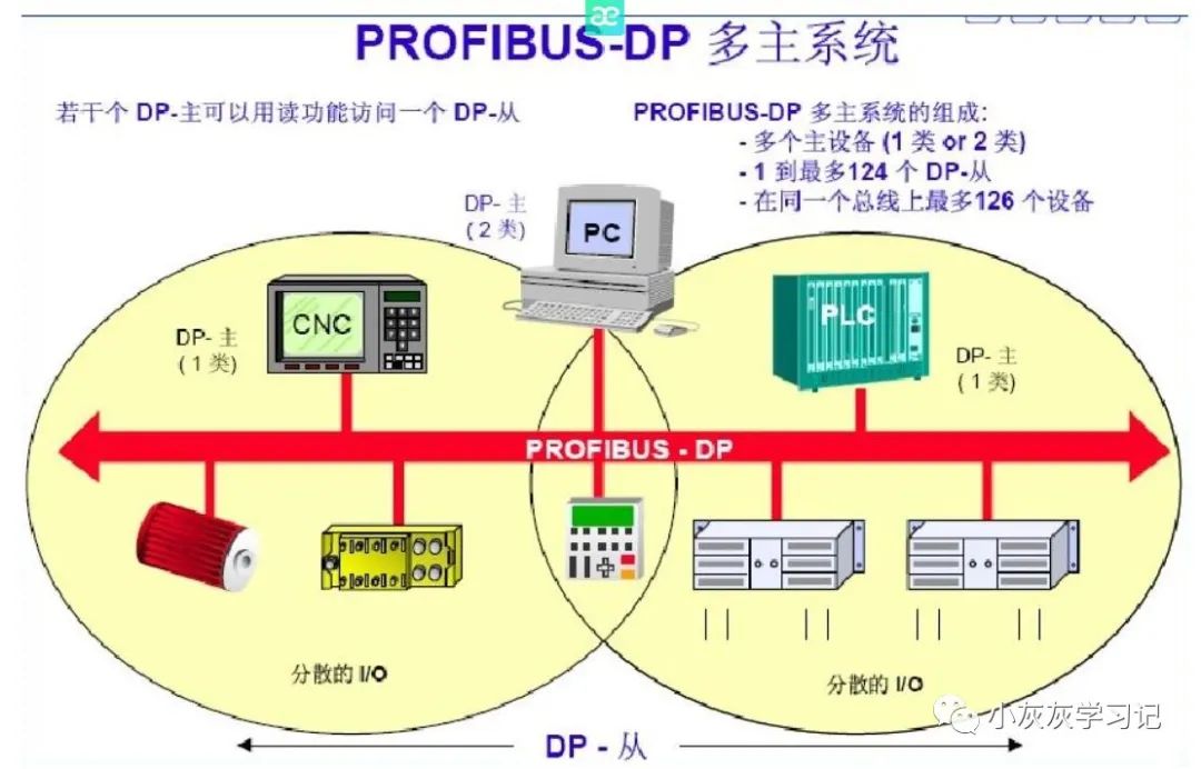
4. ProfiBus Communication
As a member of the many fieldbus families, ProfiBus is the most widely used fieldbus standard in the European industrial sector, and it is also one of the internationally recognized fieldbus standards. ProfiBus belongs to the unit level and field level of the SIMITAC network, suitable for transmitting small to medium amounts of data. Its openness allows many manufacturers to develop products that comply with the ProfiBus protocol, which can connect to the same ProfiBus network. ProfiBus is an electrical network, with physical transmission media that can be shielded twisted pairs, fiber optics, or wireless transmission. It officially became an international standard for fieldbus in 1989. PROFIBUS is an international, open, device-independent fieldbus standard, with transmission speeds selectable in the range of 9.6 kbaud to 12 Mbaud, and all devices connected to the bus must be set to the same speed when the bus system is started. PROFIBUS is widely used in manufacturing automation, process industry automation, and automation in other fields such as buildings and transportation power. PROFIBUS is also a fieldbus technology used for workshop-level monitoring and data communication and control at the field device level. It enables decentralized digital control and field communication networks from the field device layer to workshop-level monitoring, providing feasible solutions for integrated factory automation and intelligent field device implementation.
5. USS Communication
USS (Universal Serial Interface) is a communication protocol developed by Siemens specifically for drive devices, which has undergone continuous development and improvement over the years. Initially, USS was used for parameterizing drive devices, focusing more on parameter settings. It has been widely used in the connection between drive devices and operation panels, debugging software (such as DriveES/STARTER). Recently, due to its simple protocol and low hardware requirements, USS has increasingly been used for communication with controllers (such as PLCs) to achieve general communication control. (Note: USS provides a low-cost, relatively simple communication control method. Due to its design, USS cannot be used in situations with high communication speed and data transfer volume requirements. In such high-demand communication scenarios, it is advisable to choose a communication method with better real-time performance, such as PROFIBUS-DP. When designing a system, this limitation of USS must be considered. For example, in applications requiring high-speed synchronization (such as paper production lines), using USS communication control for dozens of frequency converters would yield poor results.)
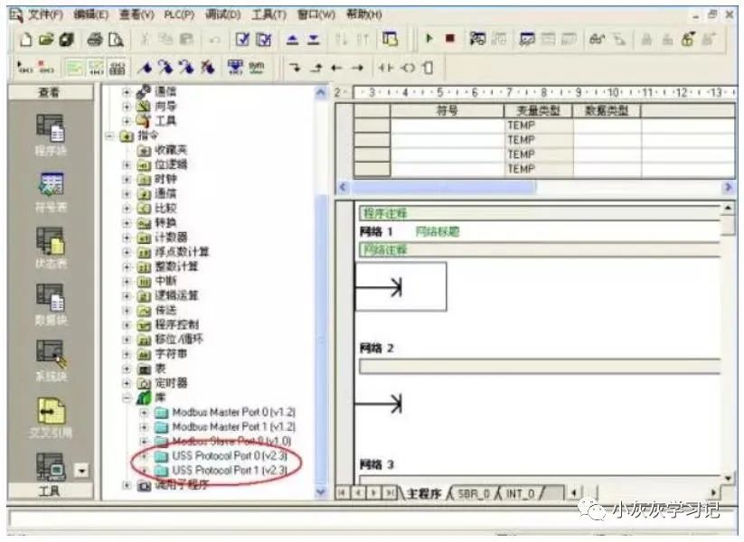
All Siemens frequency converters are equipped with an RS485 communication port, allowing the PLC to act as the master station, with a maximum of 31 frequency converters allowed as slaves in the communication network. Depending on the address of each frequency converter or using broadcast methods, access to the required frequency converters can be achieved. Only the master station can issue communication request messages, where the address character in the message specifies the slave to which data is to be transmitted; the slave can only send data to the master after receiving a request message from the master, and slaves cannot directly exchange data. Before using the USS protocol, the Siemens instruction library needs to be installed. The USS protocol instructions are located in the library folder of the STEP7—MICRO/WIN32 instruction tree, which provides 14 subroutines, 3 interrupt programs, and 8 instructions to support the USS protocol. Calling an instruction will automatically add one or more subroutines.
The basic features of the USS protocol are as follows:
Supports multipoint communication (thus can be applied on networks such as RS 485)
Utilizes a single master “master-slave” access mechanism
A maximum of 32 nodes can be on one network (maximum of 31 slaves)
Simple and reliable message format, allowing flexible and efficient data transmission
Easy to implement and low cost
The working mechanism of USS is that communication is always initiated by the master station, which continuously polls the slaves. The slaves decide whether and how to respond based on the received instructions. Slaves never actively send data.Slaves should respond under the following conditions:
1. The received master message has no errors;
2. And this slave is addressed in the received master message.