

A weighing instrument that supports the Modbus protocol
You can adjust according to your requirements, as long as it matches with the PLC side
Baud rate: 9600
Data format: 8n1: 8 data bits/no parity bit
Communication method: Modbus protocol
Checksum: OFF
Instrument communication address: 1
Here we only need to read the current real-time weight of the instrument

The address for the real-time weight of the instrument is 0, corresponding to 40001 in Modbus communication
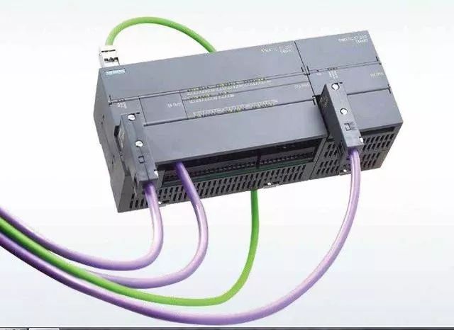
200smartPLC
Connect the RS485 interface A, B of the instrument to the DB9 interface of the PLC (DB9 interface 3 is A, 8 is B)
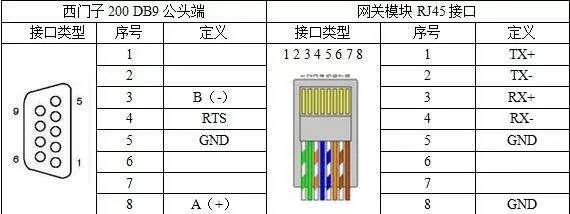
I remember that 3 is A, 8 is B, not sure why this image is like this, but it doesn’t matter, if different, just swap the two wires
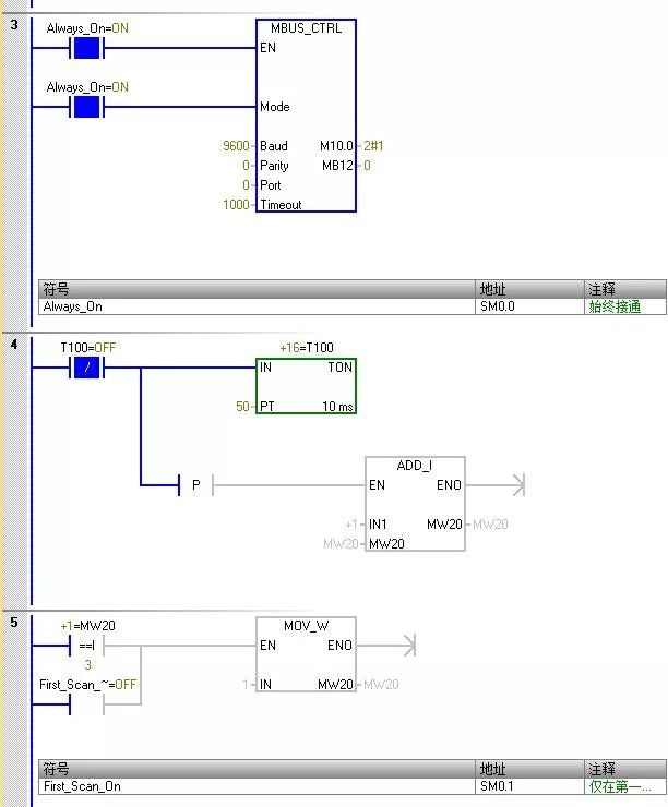
Preparation work is complete, now we can start our PLC programming. Since the 200smart software itself includes the Modbus protocol library, we do not need to add it separately. Below is an introduction on how to program.
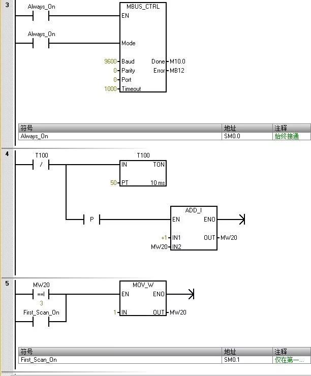
The value entered for “Mode” is used to select the communication protocol. When the input value is 1, the CPU port is assigned to the Modbus protocol and the protocol is enabled.
The parameter “Parity” should be set to match the parity of the Modbus slave device. 0 (no parity)
The parameter “Port” sets the physical communication port (0 = RS-485 integrated in the CPU).
The parameter “Timeout” is set to the number of milliseconds to wait for the slave to respond. A typical value is 1000 ms (1 s).
When the MBUS_CTRL command is completed, the command will return “true” to the “Done” output.
The “Error” output contains the result of the command execution.
The above parameter settings correspond to those on the weighing instrument side
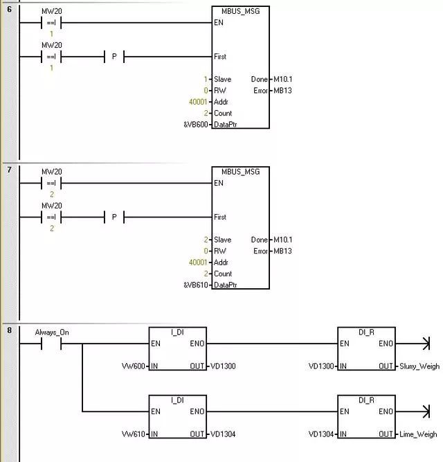
The parameter “Slave” is the address of the Modbus slave device. The allowed range is 0 to 247. Address 0 is the broadcast address. Only use address 0 for write requests. The system does not respond to broadcast requests to address 0. Not all slave devices support the broadcast address. The S7-200 SMART Modbus slave library does not support the broadcast address.
Use the parameter RW to indicate whether to read or write this message. 0 (read)
The parameter address (Addr) is the starting Modbus address. The register address is 0, corresponding to address 40001 in Modbus communication
The parameter “Count” is used to allocate the number of data elements to be read or written in that request. Read the number of holding registers in the instrument.
The parameter DataPtr is an indirect address pointer that points to the V memory in the CPU related to the read request. Set DataPtr to the first CPU memory unit for storing data read from the Modbus slave.
Data from instrument at address 1 is stored in VW600, and data from instrument at address 2 is stored in VW610.
Programming is complete, now let’s look at the monitoring effect.
The master station initialization command runs normally, with no errors
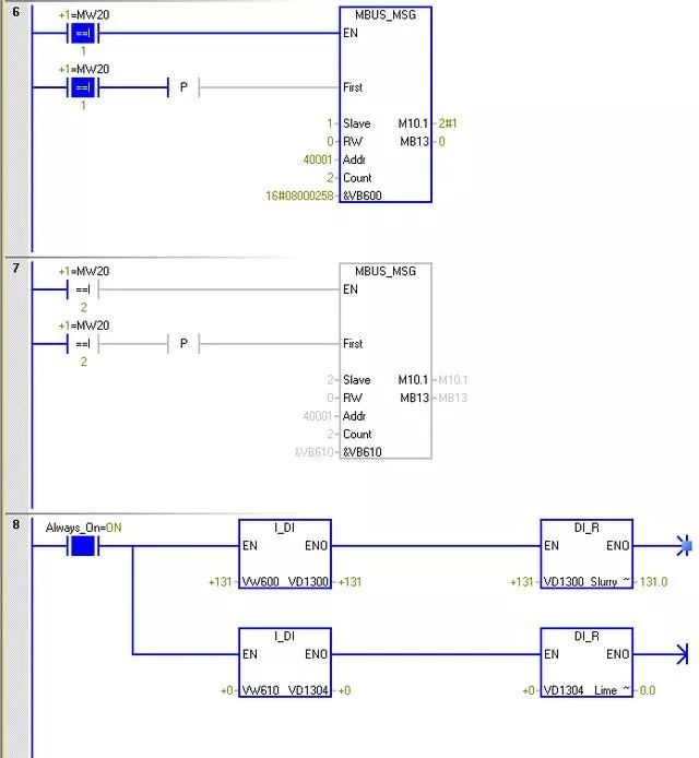
The data for instrument at address 1 is 131, and the data for instrument at address 2 is 0
来源:网络,版权归原作者所有


往期推荐


1、2021最新完整版电工题库(国家版)


2、电气高手私藏工具包(电工仿真软件+16套电气行业PPT)


3、师傅说:不会CAD就别想当电气工程师了(附CAD软件包)


喜欢点这里


免费学PLC和电工课程,点阅读原文